Kevin's Woodturnings
 MISCELLANEOUS
TOOLS & JIGS
MISCELLANEOUS
TOOLS & JIGS
Click on the hyperlink below to jump to the section:
- Bowl Assembly Using
Rubber
Chuckies
- Centering Donut Chuck for
Reverse Turning
Half-Ring
Trim Jig
- Bowl Wall Thickness
Calipers
- Segment
Ring Press
- Lathe
Sanding Hood
- Table
Saw Blade Angle Vernier Pointer
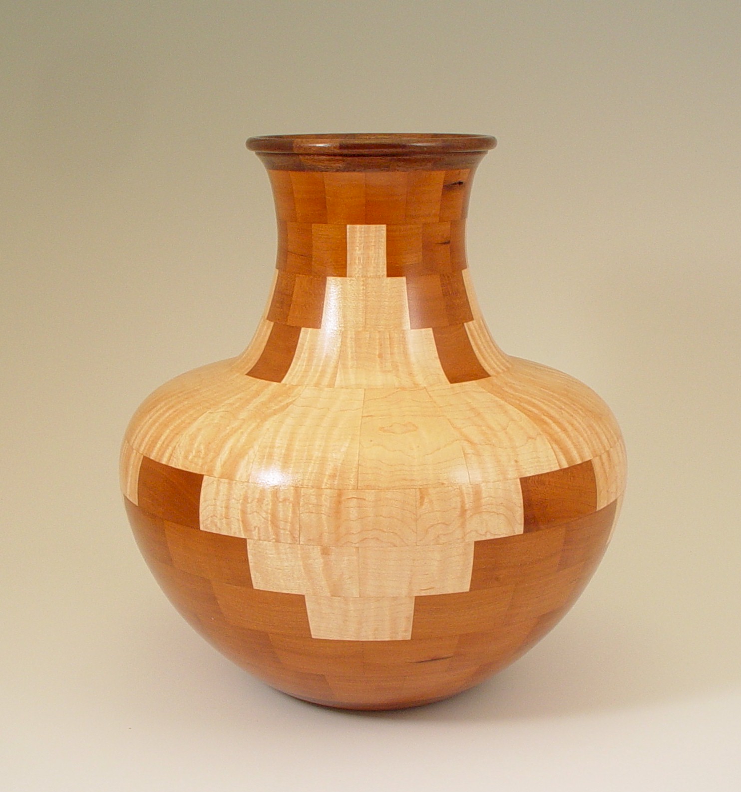
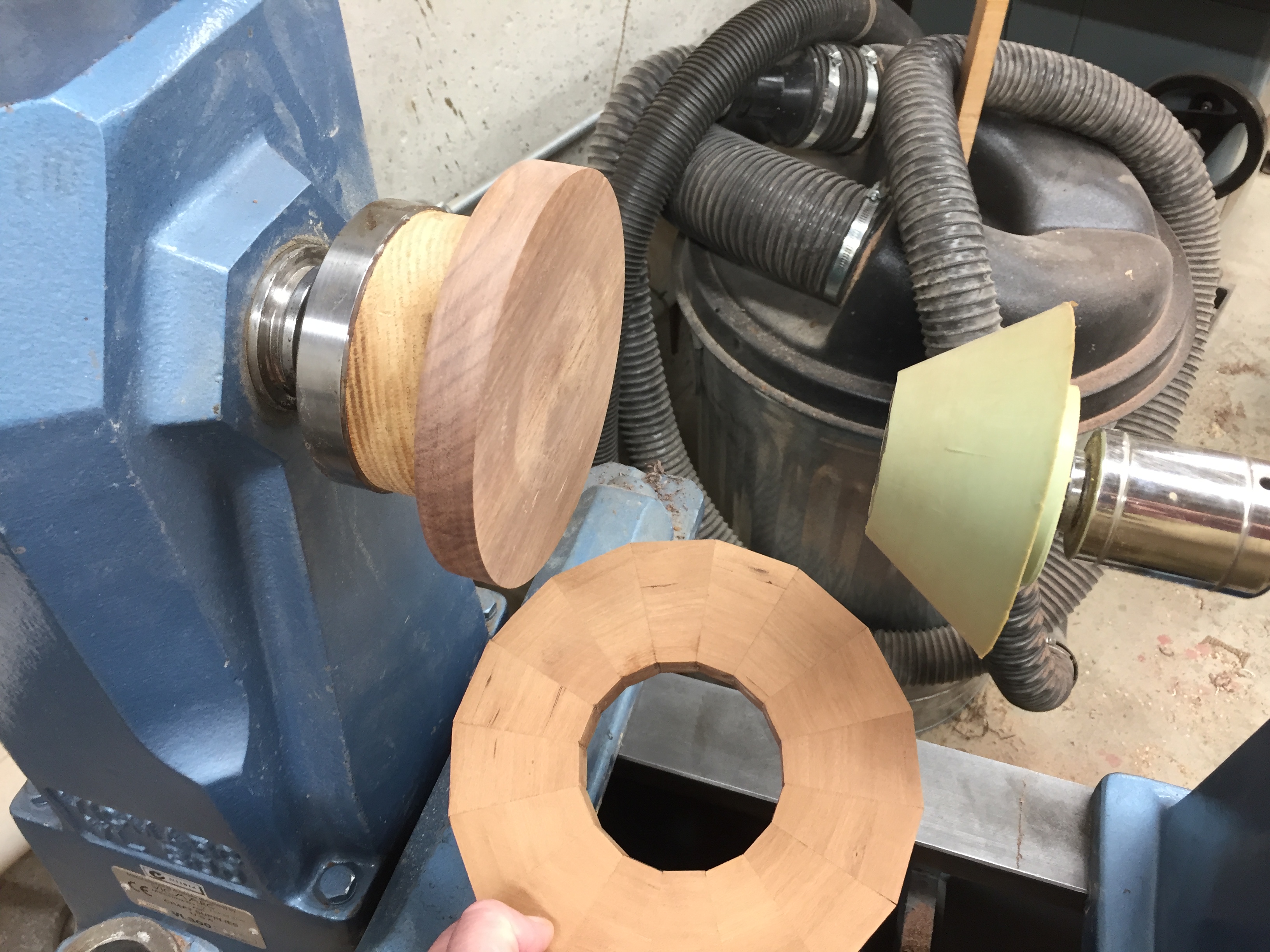
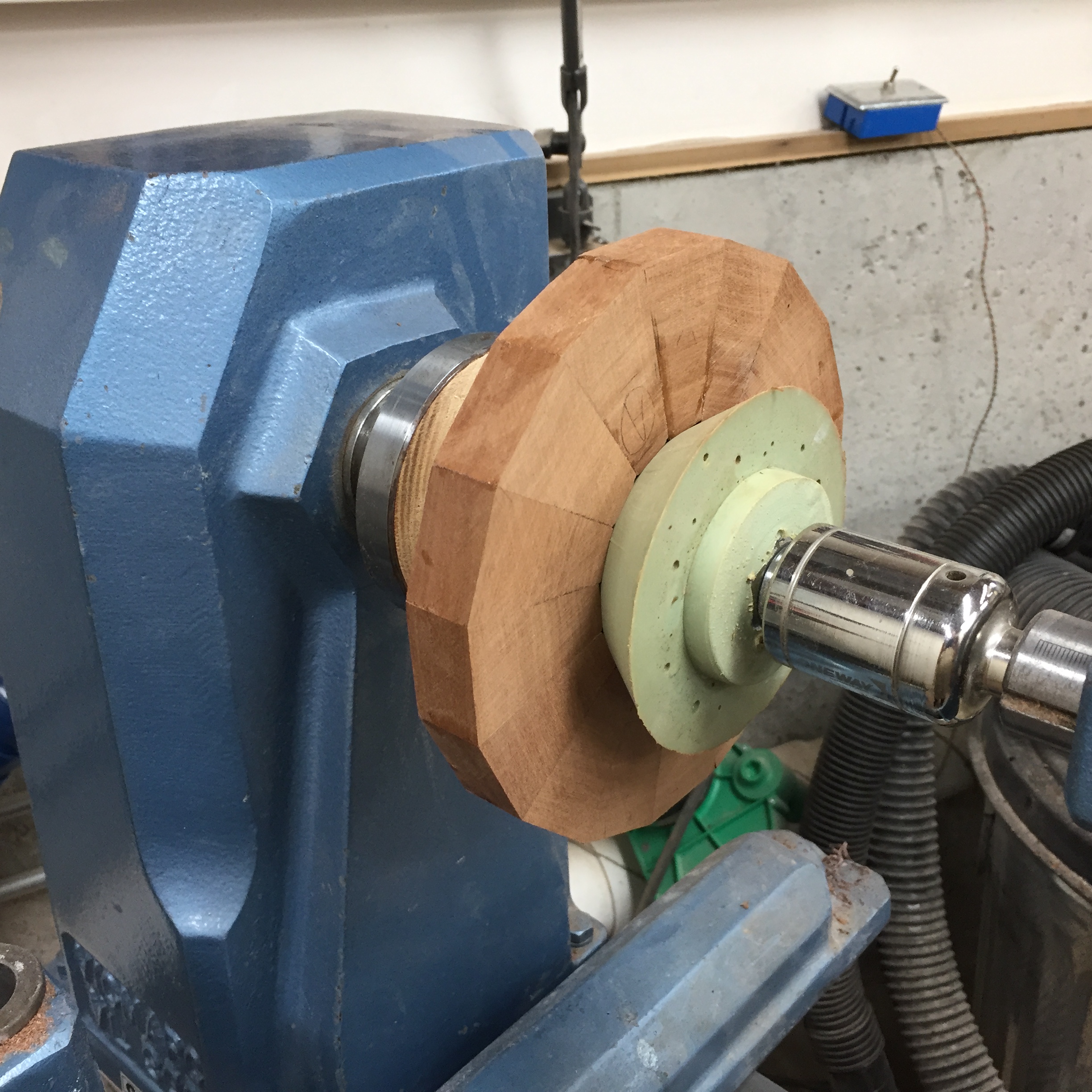
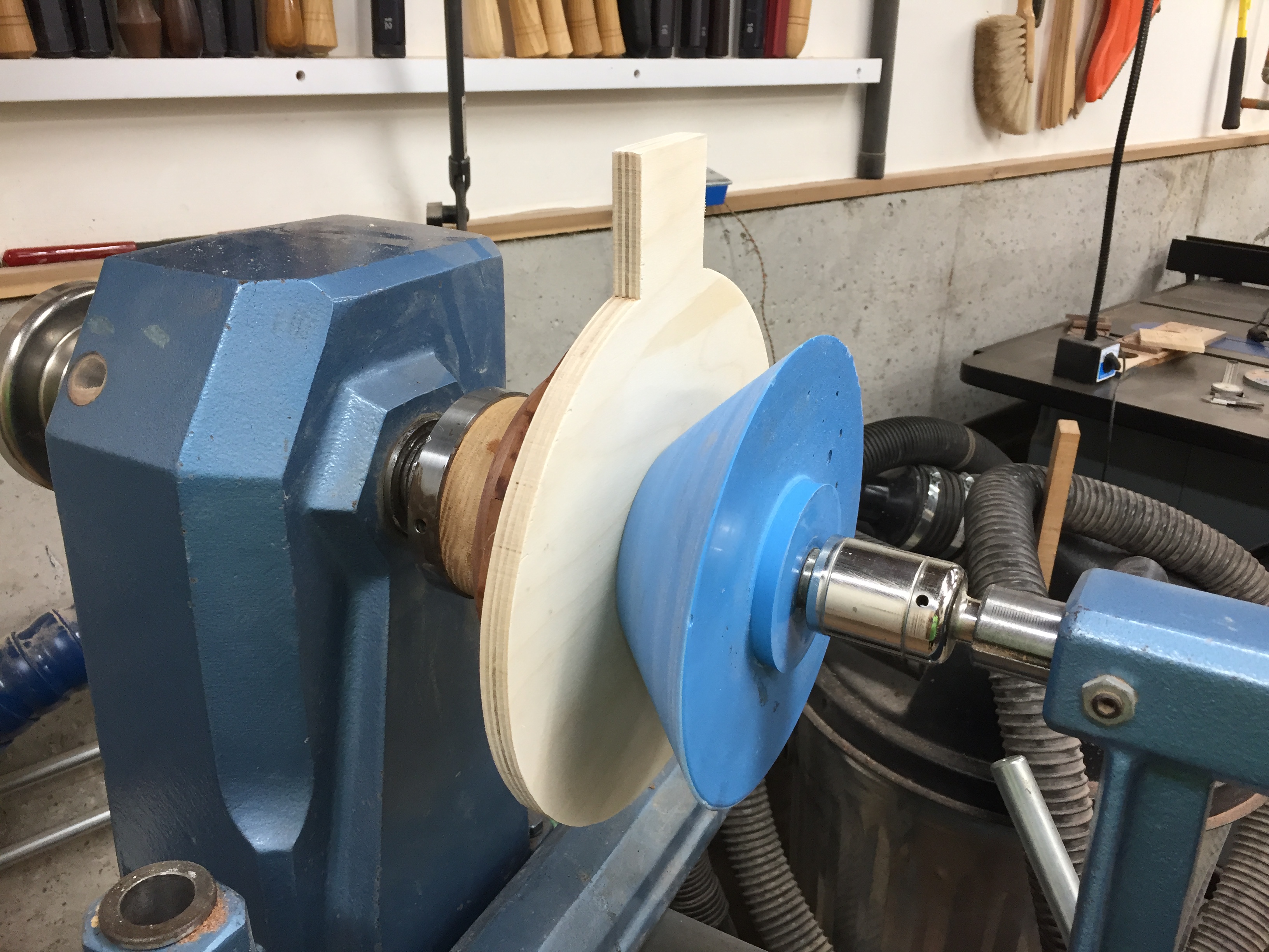
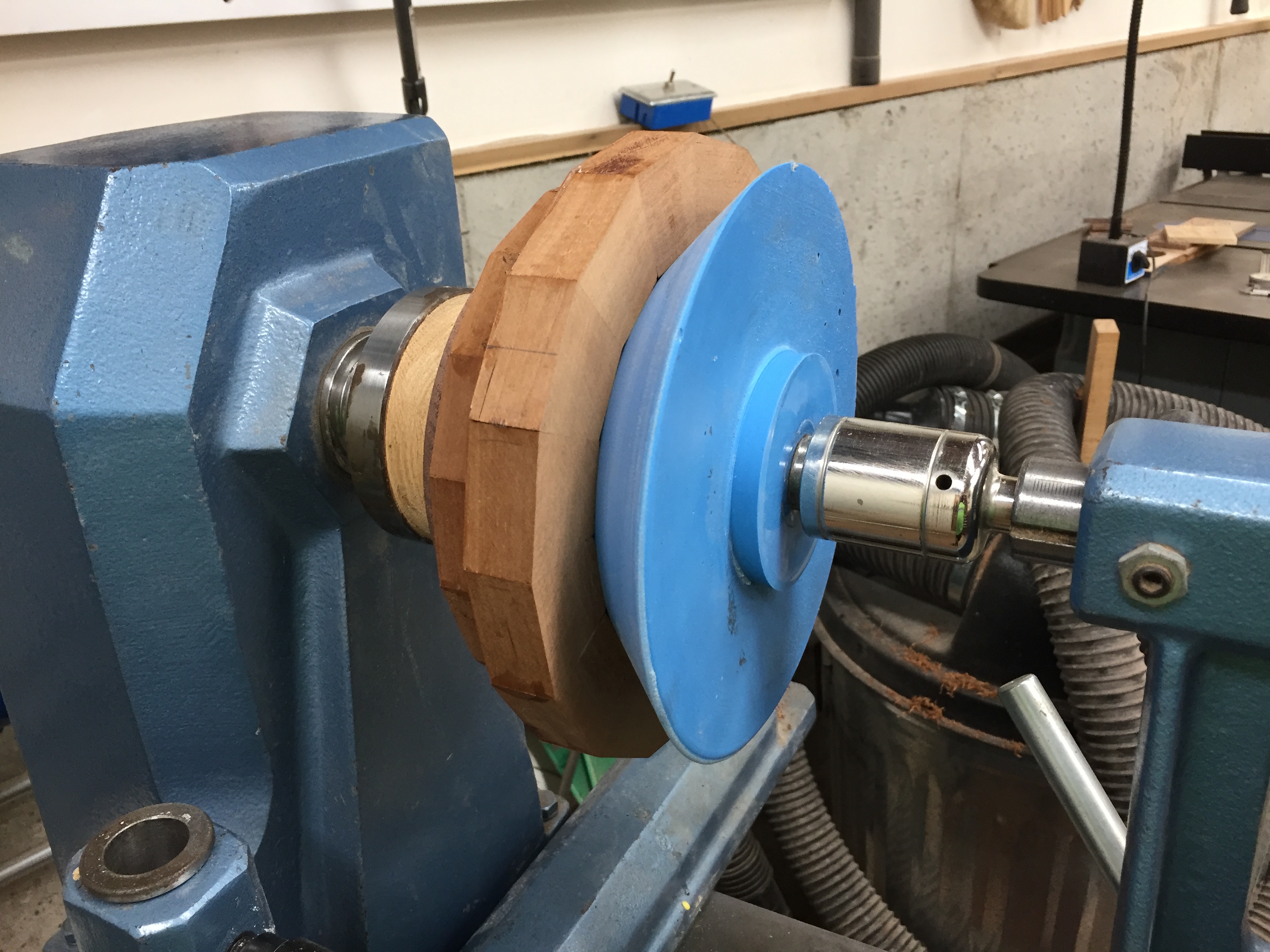
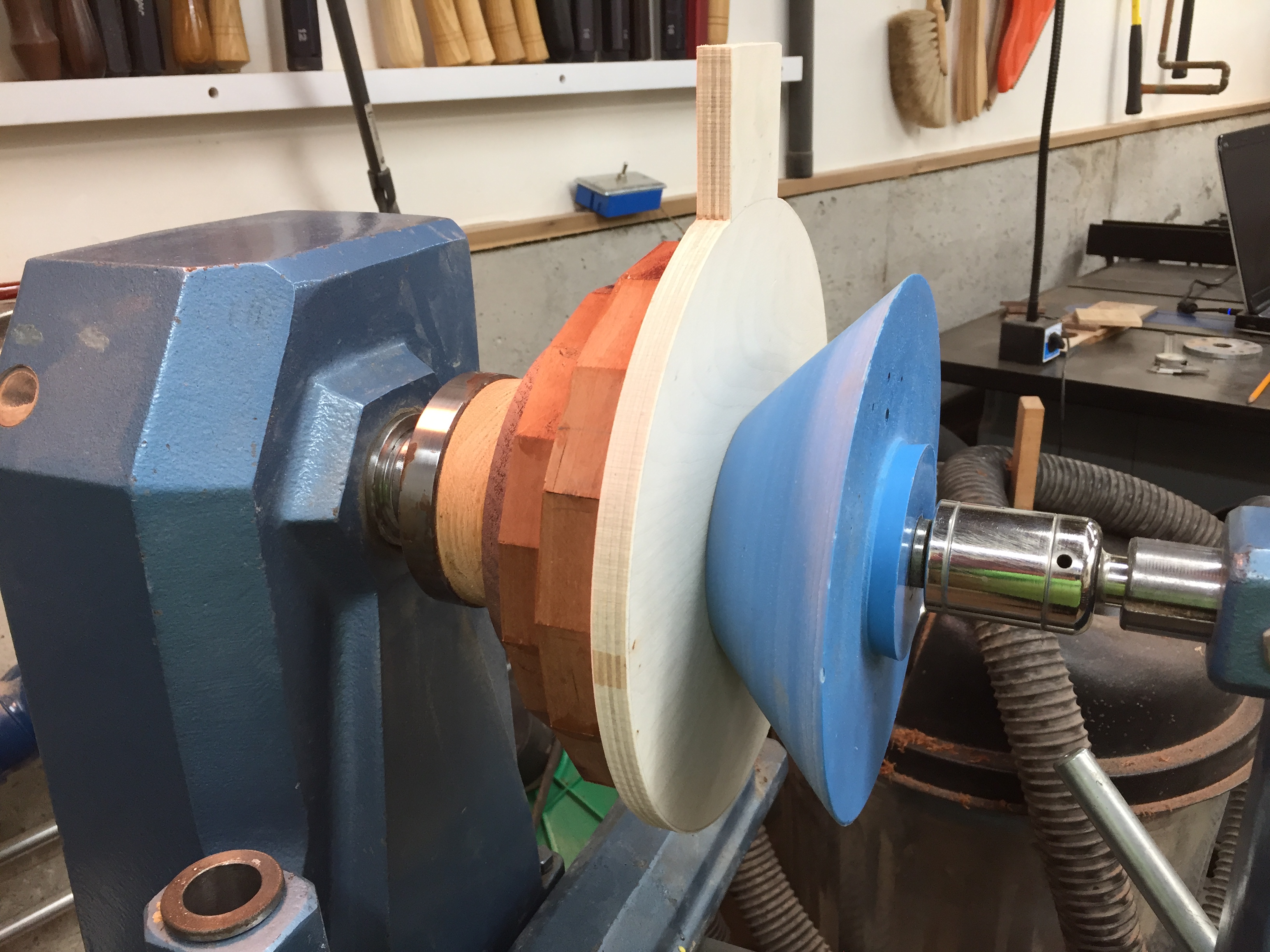
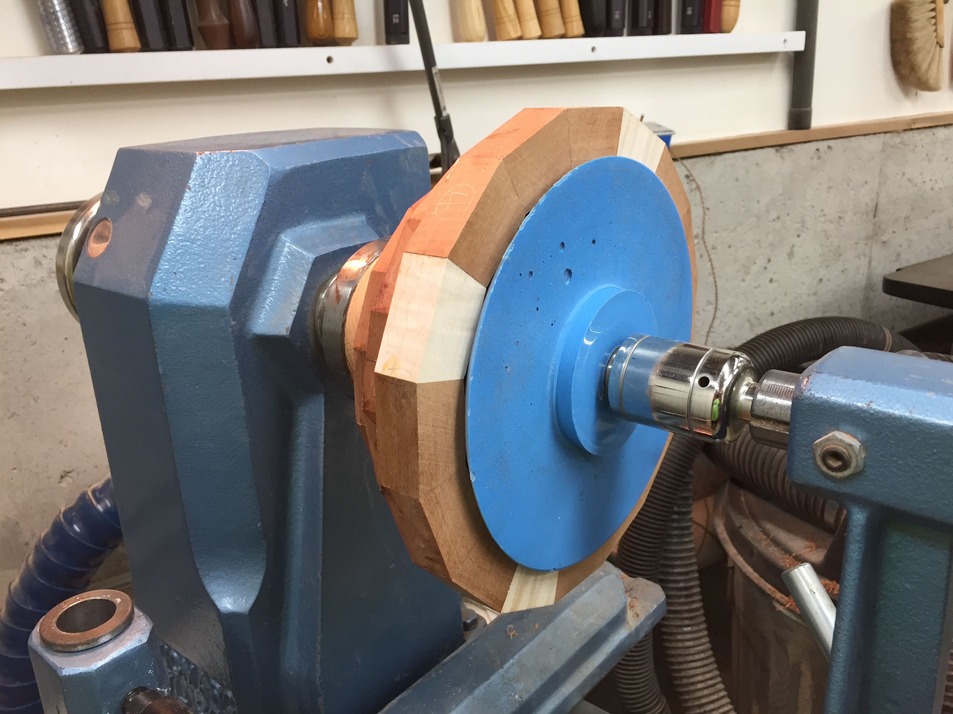
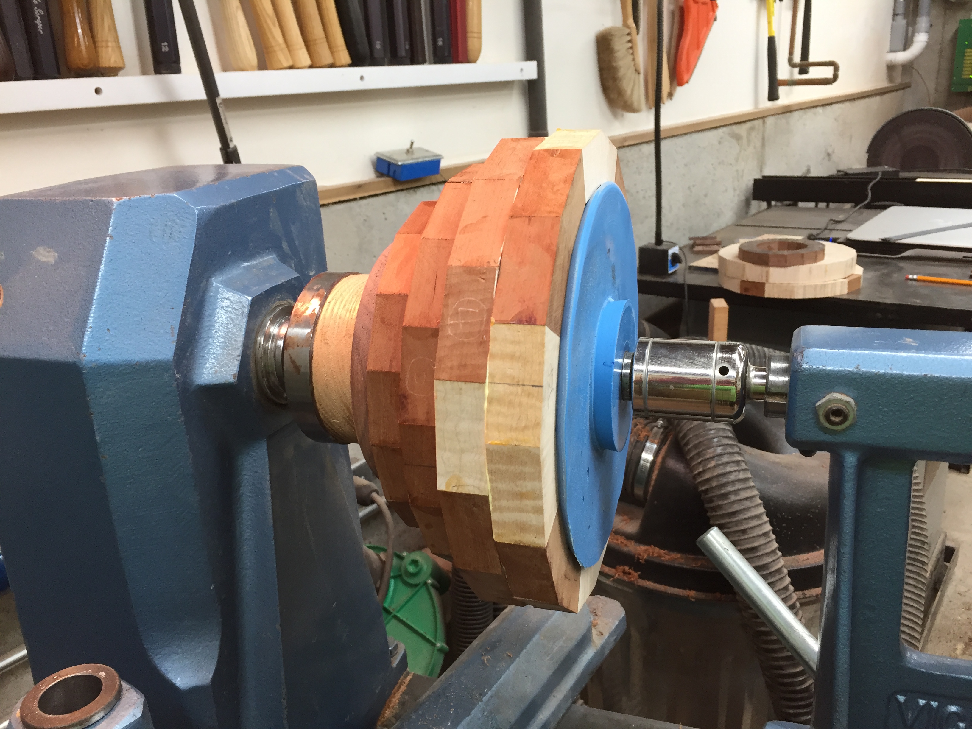
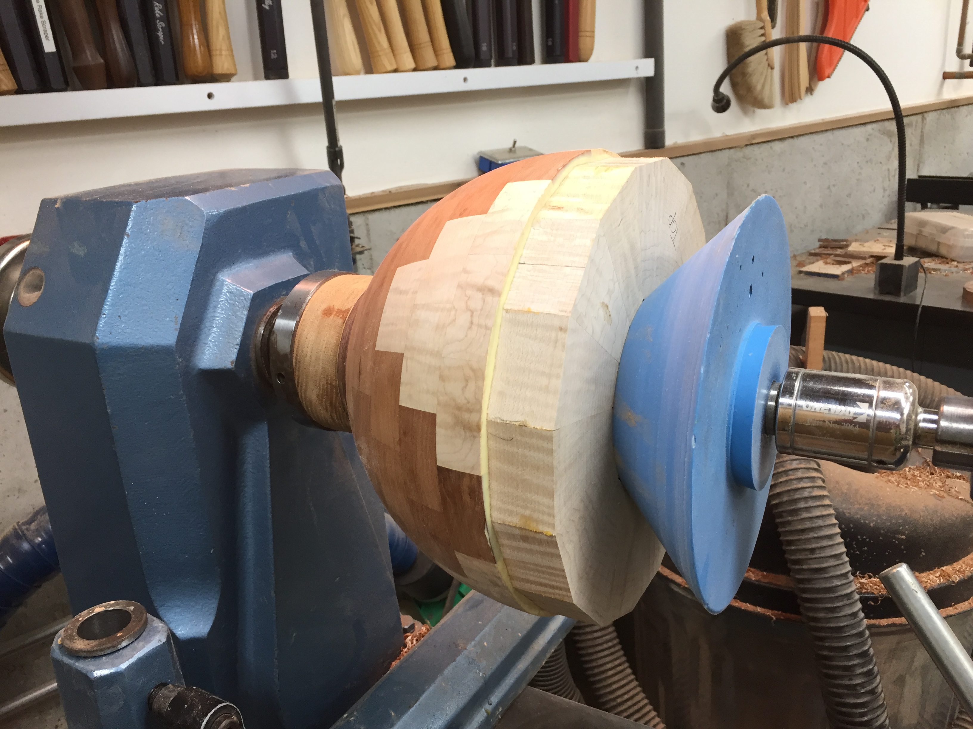
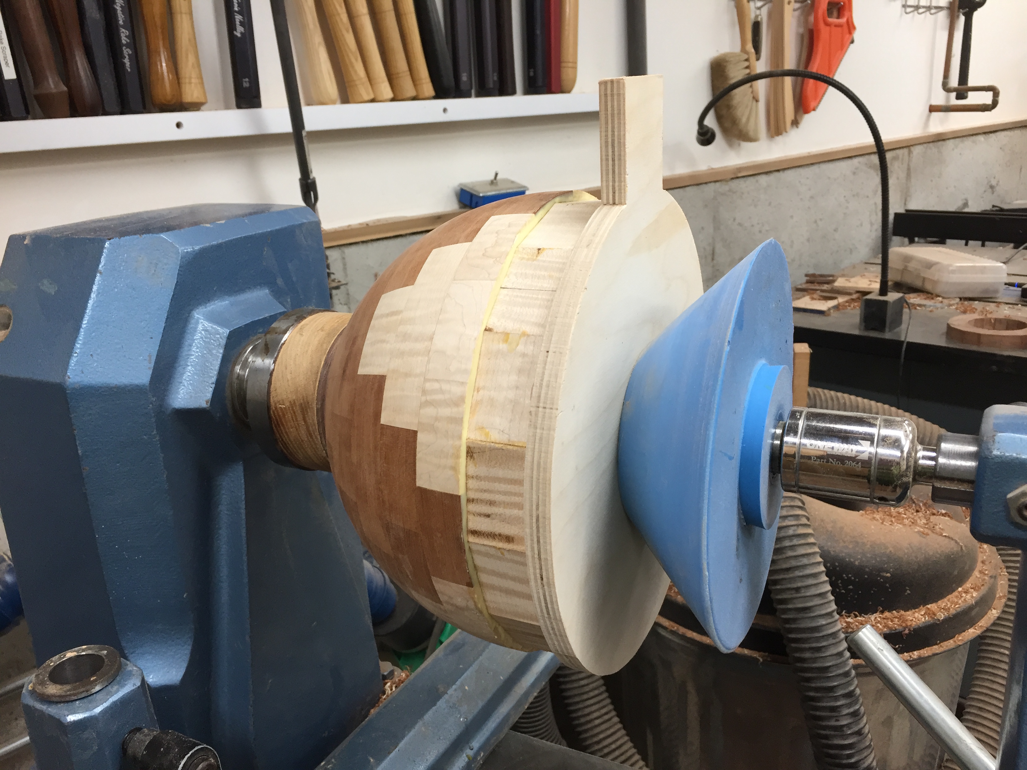
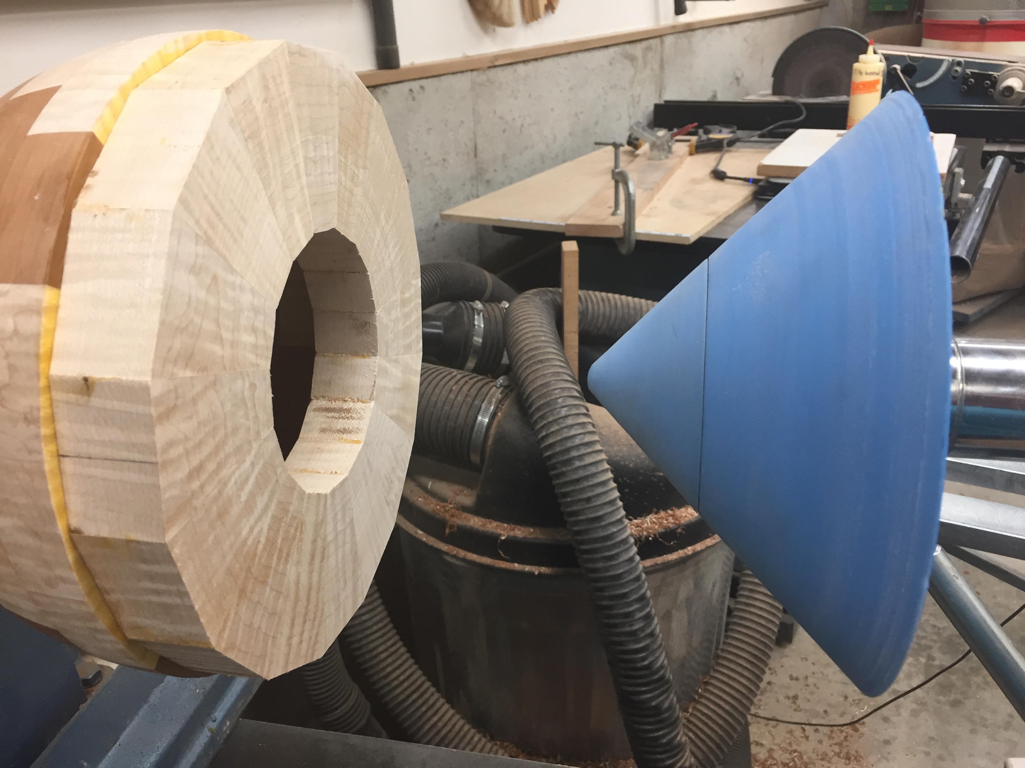
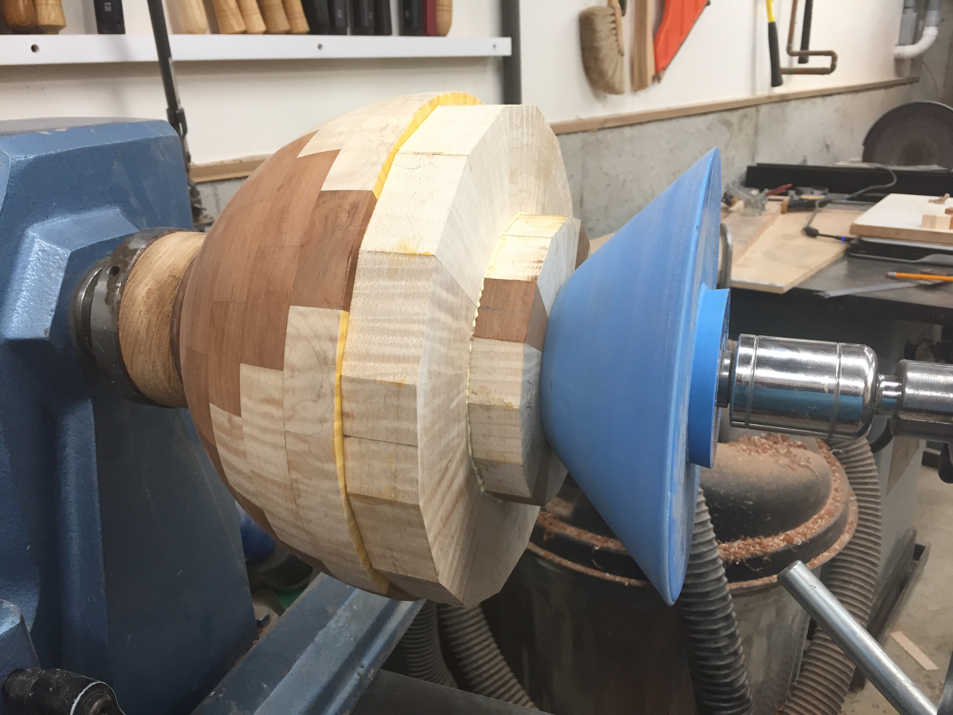
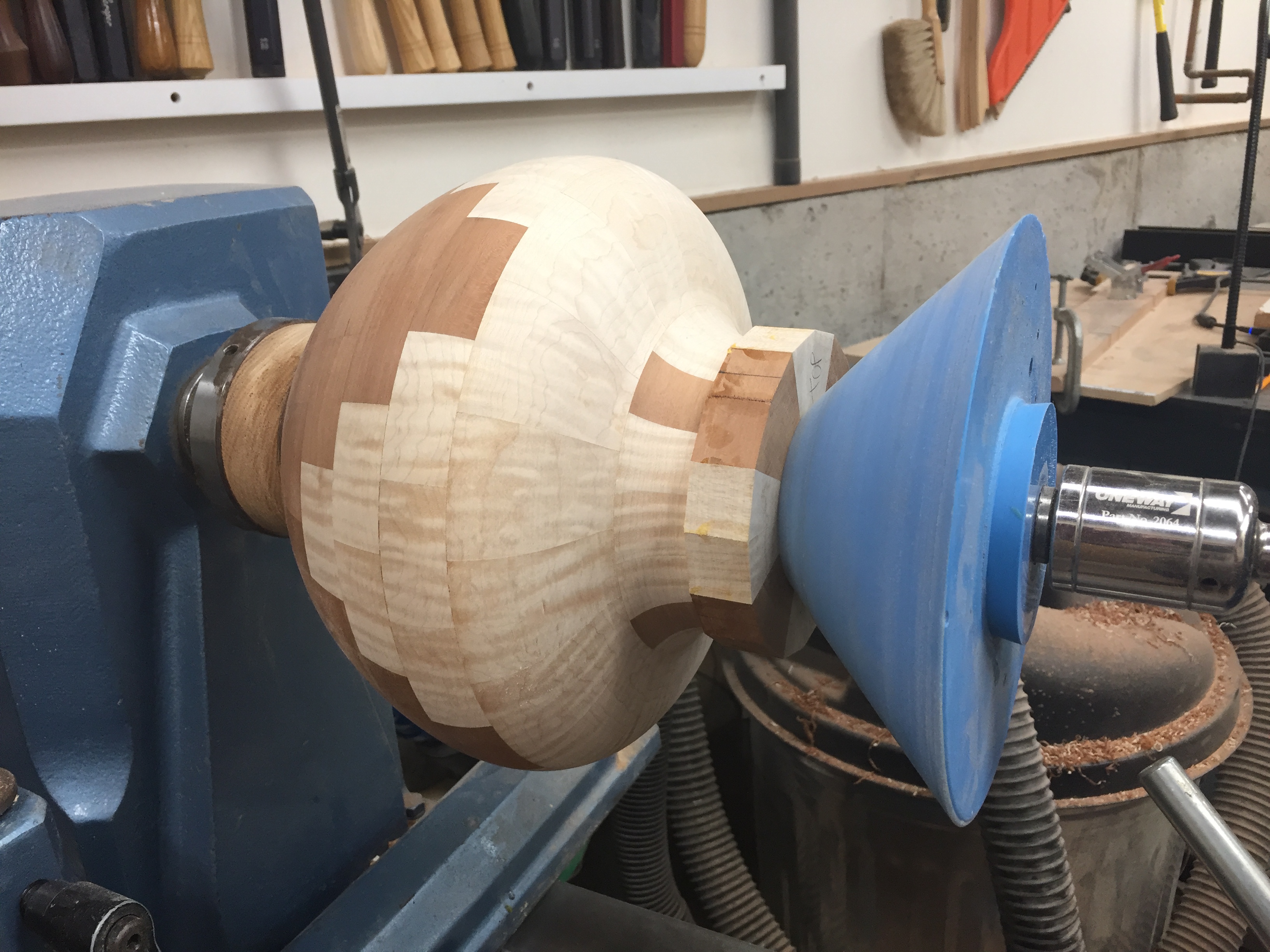
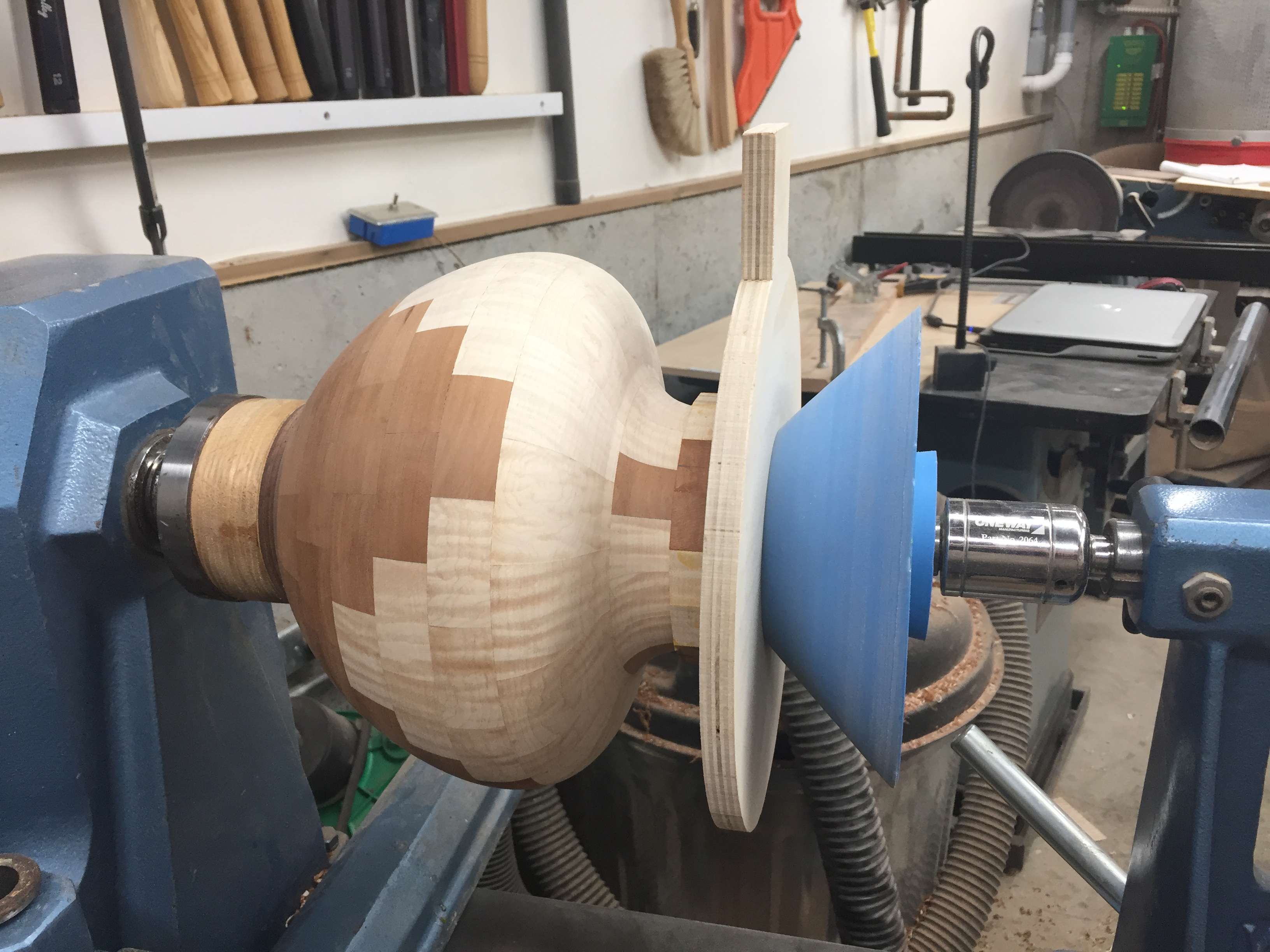
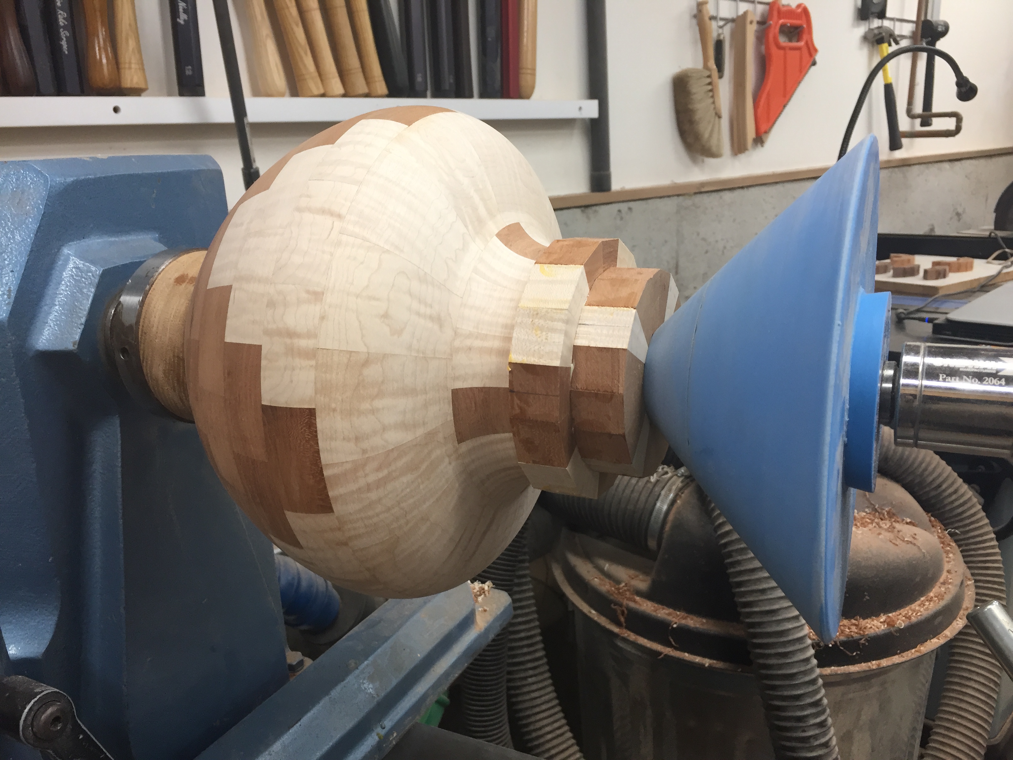
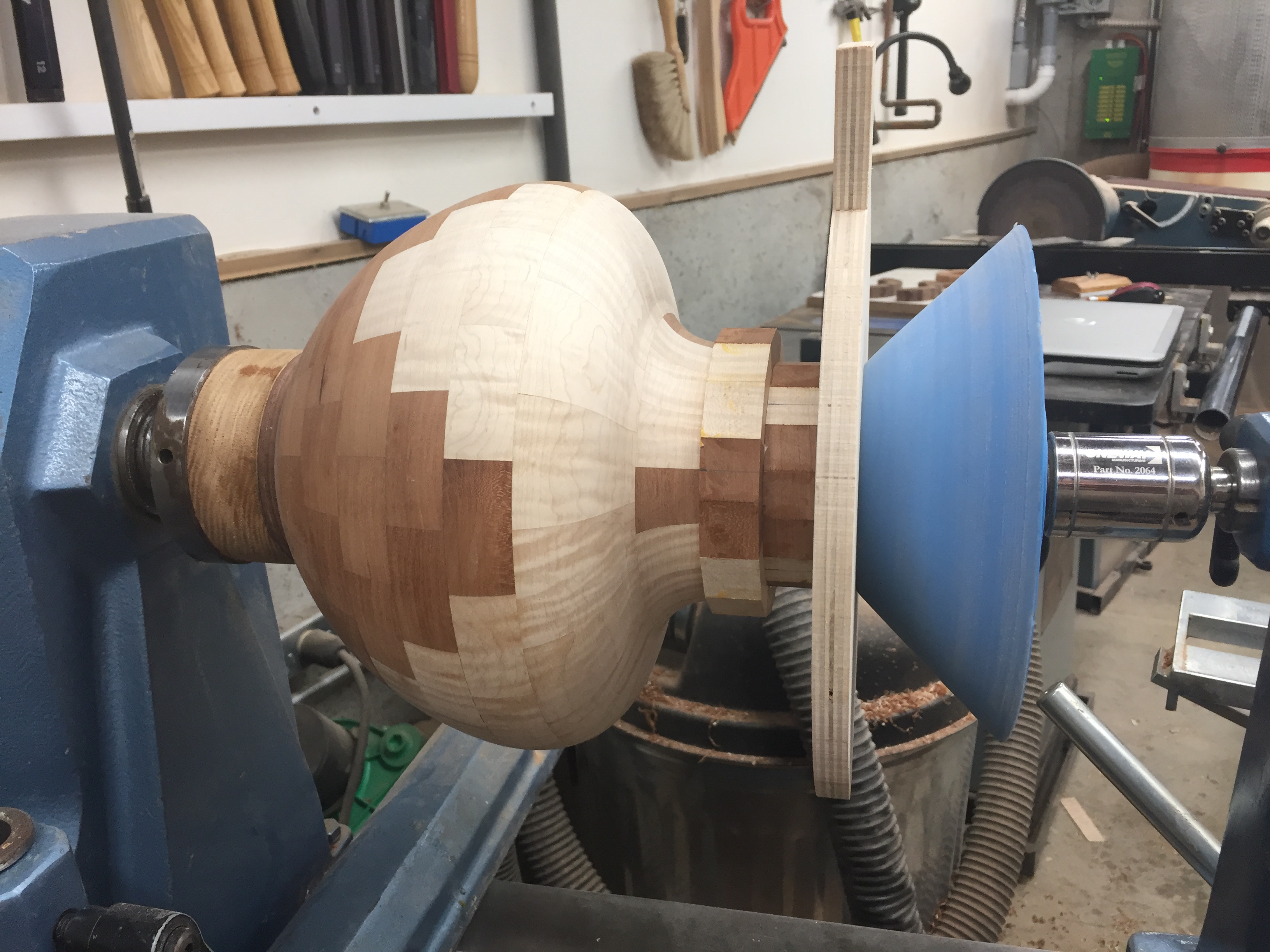
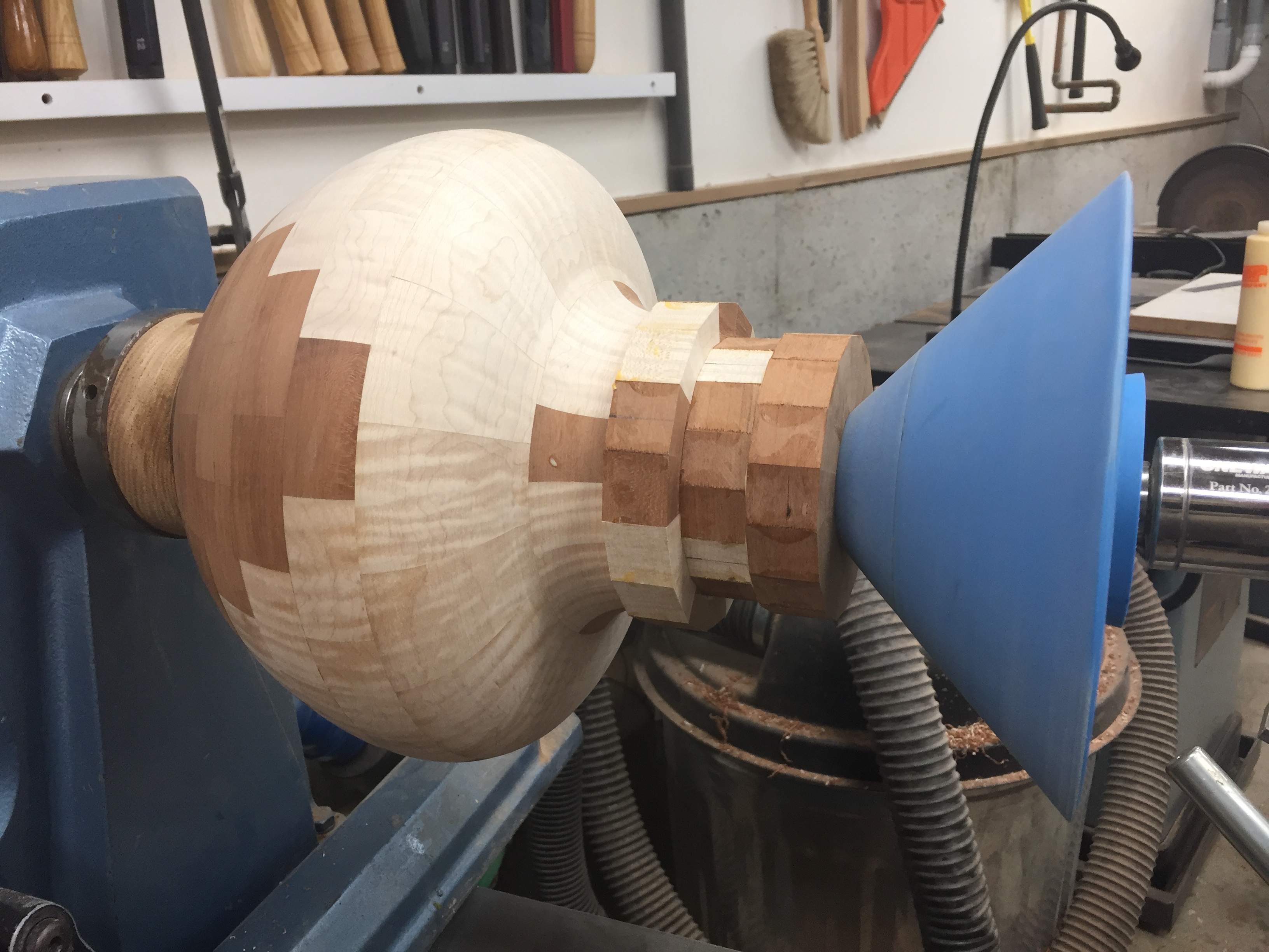
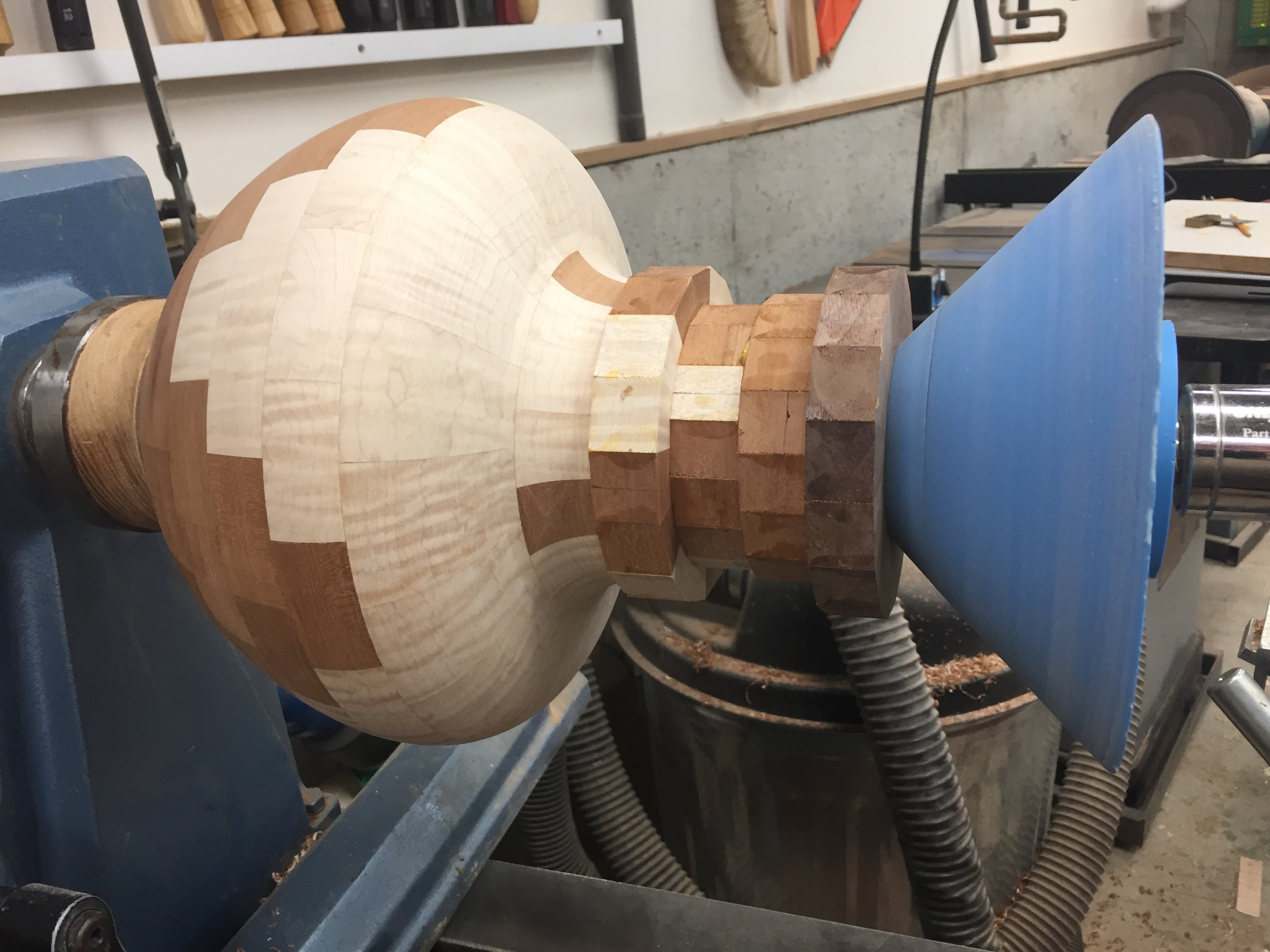
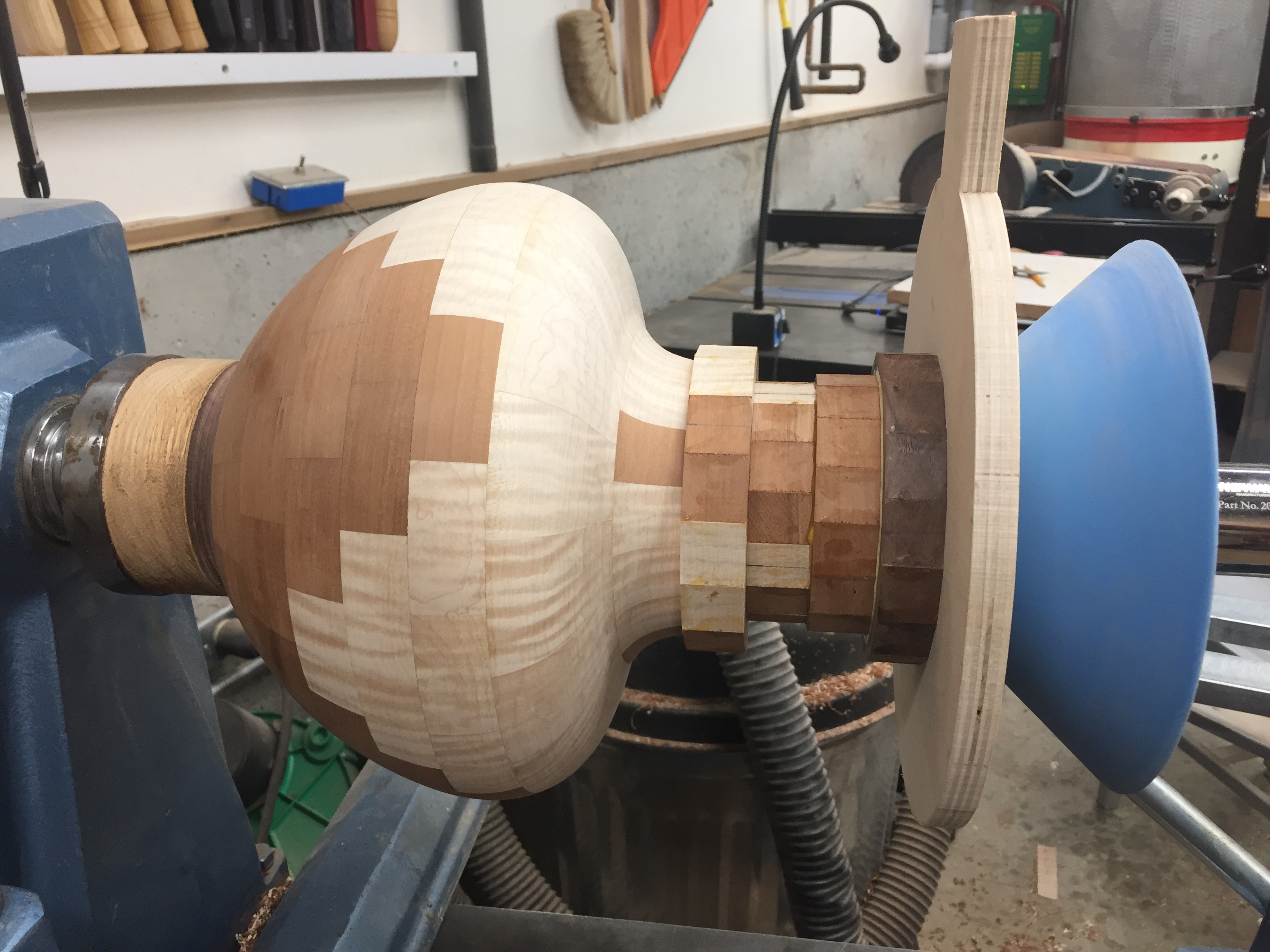
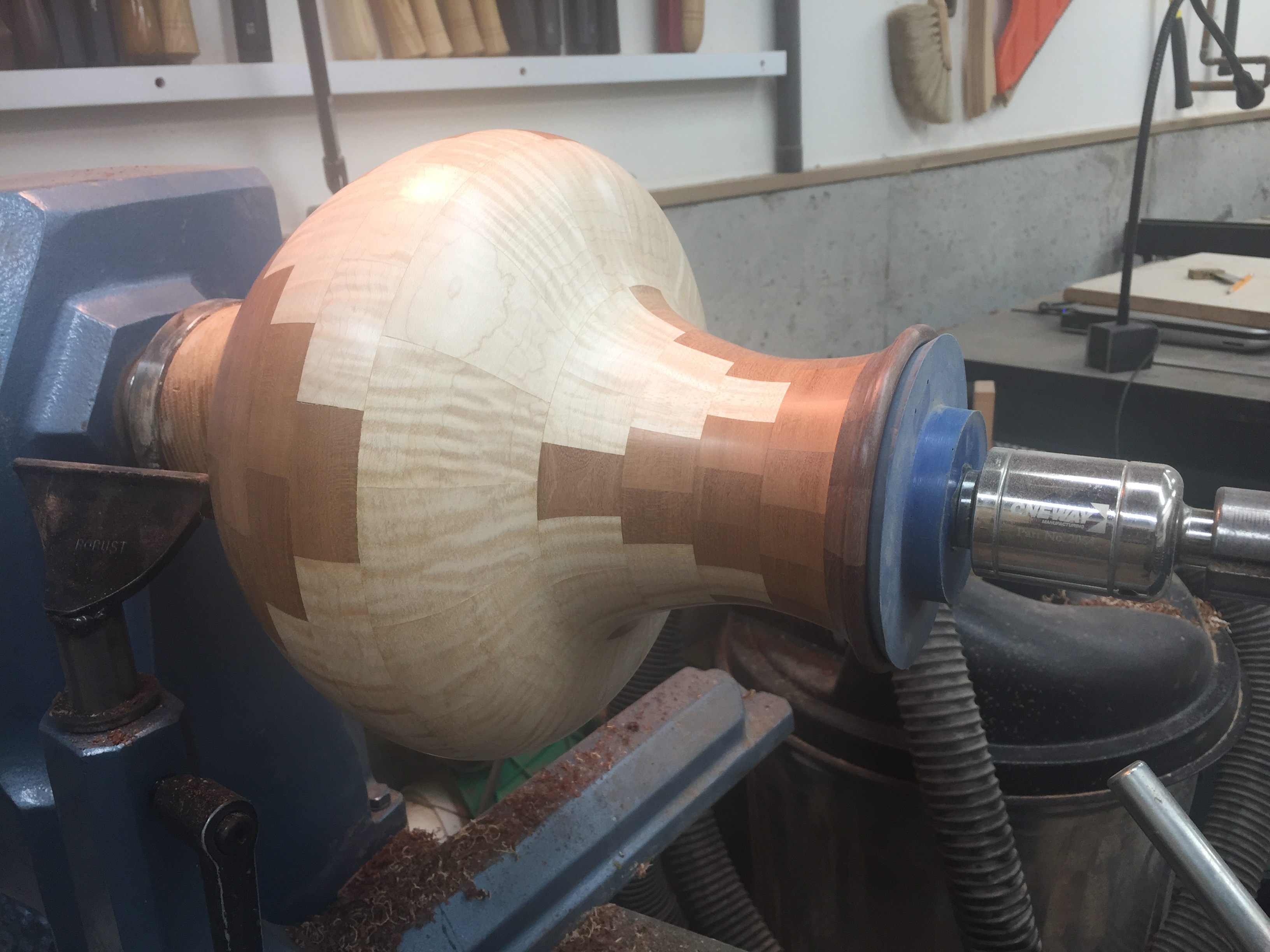
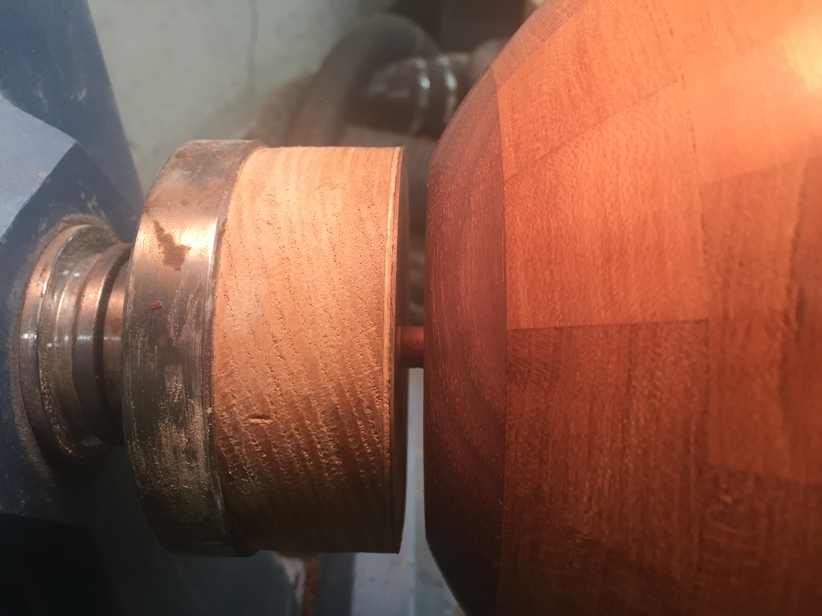
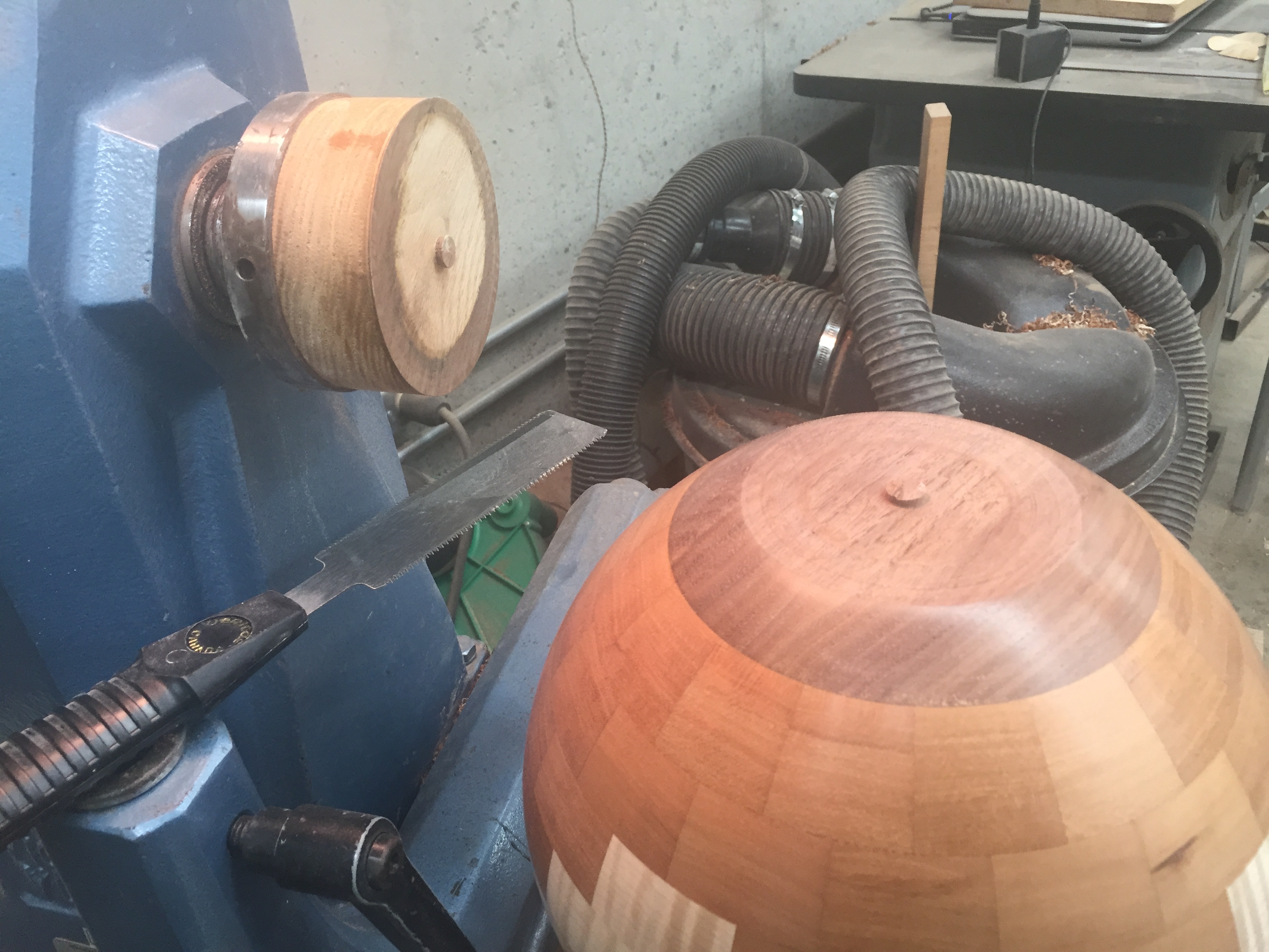
Bowl Assembly Using Rubber Chuckies
These photos show how I assembled my Bowl #859 using several
different kinds of Rubber Chuckies. During construction, I usually
remove my bowl from the lathe and clamp rings using my ring press.
Using this Rubber Chucky method, I never removed my bowl from
the lathe until I cut it off the faceplate. Rubber
Chuckies have many uses. They are great non-marring centering
cones. Rubber Chuckies can be
purchased from Don Doyle at www.rubberchucky.com
Click on
the picture for an
enlarged view.
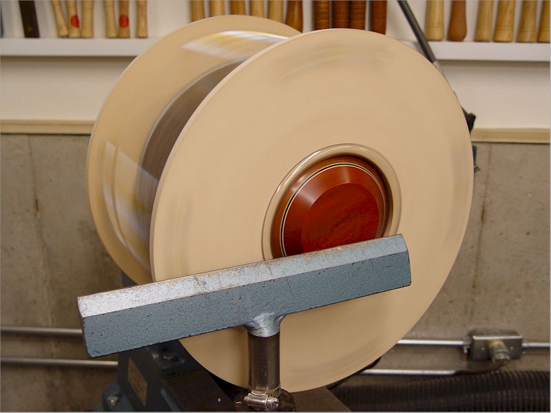
Centering
Donut Chuck for Reverse
Turning
Donut chucks and cole jaws have both been around for
a long time. I decided to combine them to make a new
version
of
a donut
chuck that centers the turning. A donut
chuck is used to hold the turning
reversed so the bottom
can be turned. One problem with
a donut chuck is that it doesn't center the piece very well.
Cole
jaws are used to grip and center a turning, but they only work
well
if the turning's chucking diameter is much wider than the
turning
height, like a
salad bowl or a platter. For example, cole jaws could only be
used
with vases if the lathe tailstock was used to secure
them.
Almost all of my turnings are glued to a faceplate,
so when I
part them off I need to finish turn the bottom. I
decided to
not completely reinvent the wheel so I combined a donut chuck with a
Nova chuck. With this fixture, cole jaws in
a Nova
scroll chuck are used to center the turning (the turning lip must be
flat). The cole jaw's buttons do not need to be very tight
against the bowl lip, just tight enough to center the
turning.
The turning is held tight against the cole jaws with the donut chuck
framework.
For turnings with small
lips, there is no
reason why the standard steel Nova chuck jaws could not be used rather
than cole jaws. Although, I would recommend
softening the
steel jaws with tape so your turning isn't marred.
This reverse turning
fixture is designed with
minor turning in mind, such as a recess in the bowl base. If
you
are doing major turning of the bowl base, you should should consider
using your tailstock to secure the bowl for the majority of the
turning, then remove the tailstock to turn the remainder of the
recess. Also be aware of the RPM limit
recommendation of the
cole jaws.
This centering donut chuck was made from two 15"
diameter
disks of 3/8" baltic birch plywood and can accommodate a 12"
diameter bowl. I chose 15" diameter disks because that is 4"
larger that the largest diameter of the cole jaws (11"). If
you
have larger cole jaws or wish to accommodate larger diameter bowls,
just made the disks larger.
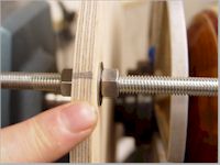
The four 10-1/2" threaded rods were cut from a 48"
length of
3/8" allthread. Depending on the height of your bowl, you
will
likely need several different lengths of threaded rods for different
bowls. Four 3/8" t-nuts, twelve 3/8" nuts and twelve 3/8"
washers
were used as well as a 12" length of 3/4" clear plastic
tubing.
Click on
the picture for an
enlarged view.
|
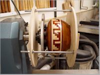
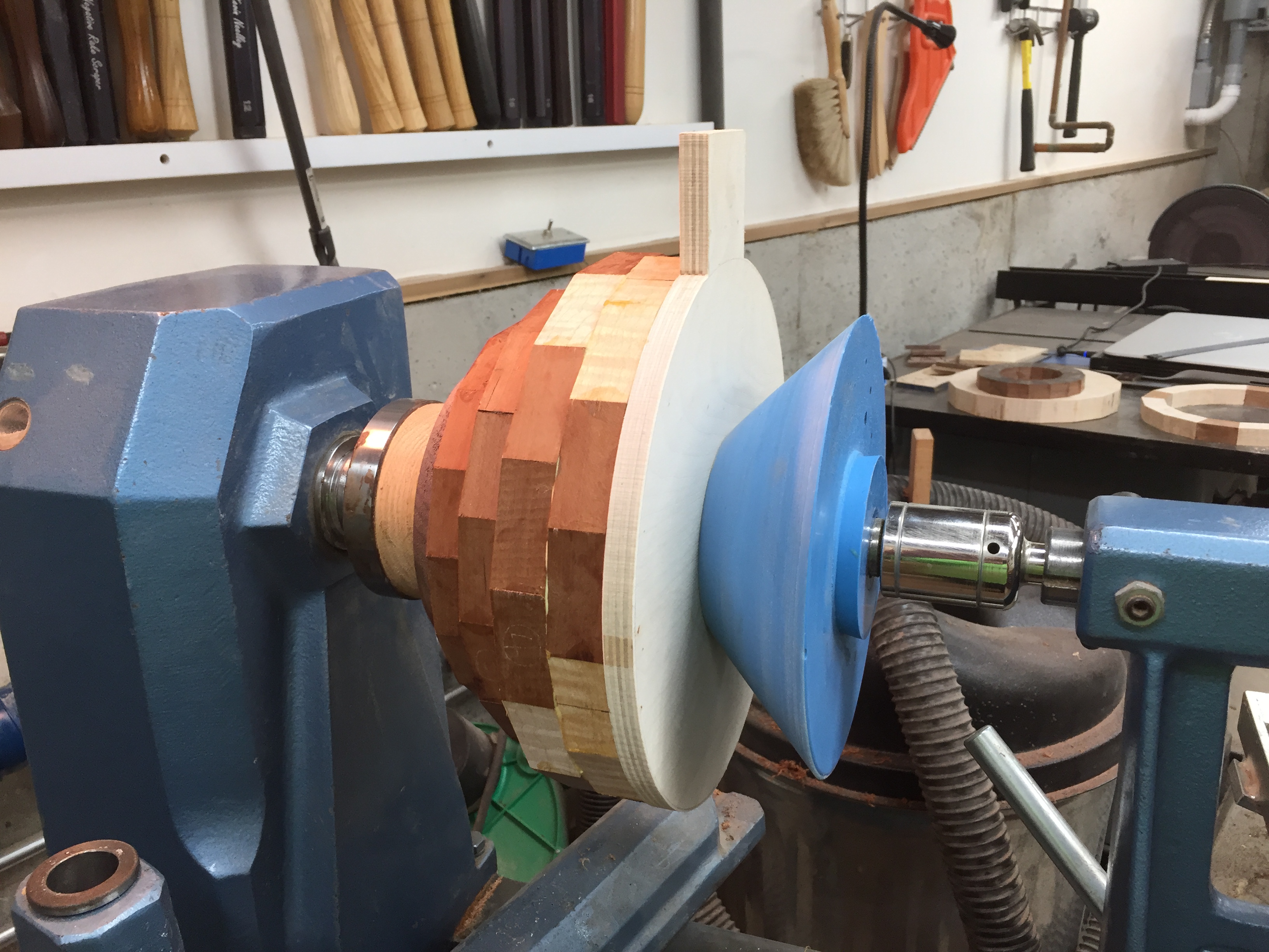
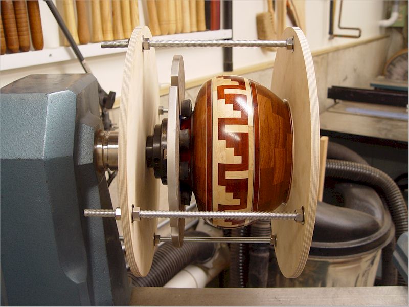
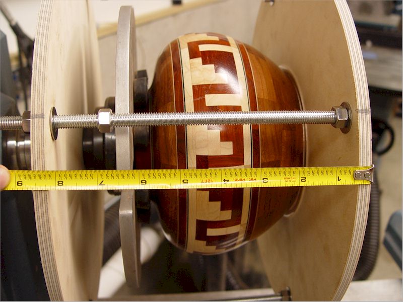
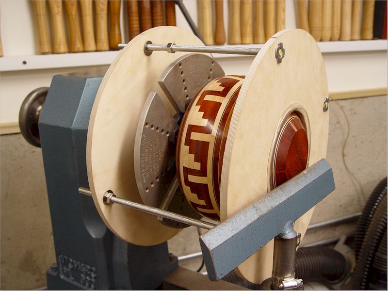
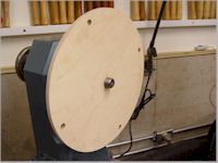
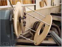
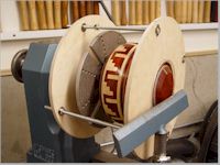
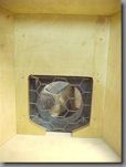
1. This is a photo of the centering donut
chuck with a bowl
mounted. This bowl is about 6" tall with a 4" diameter lip,
so it
couldn't be turned just using cole jaws. Also the bowl does
not
have a graspable lip.
|
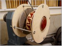
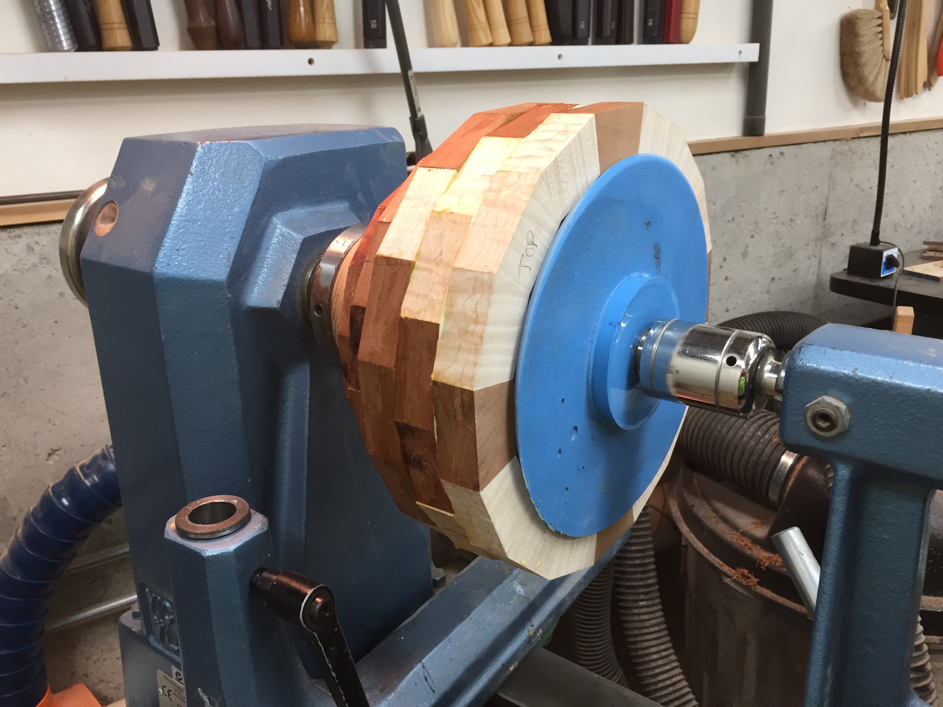
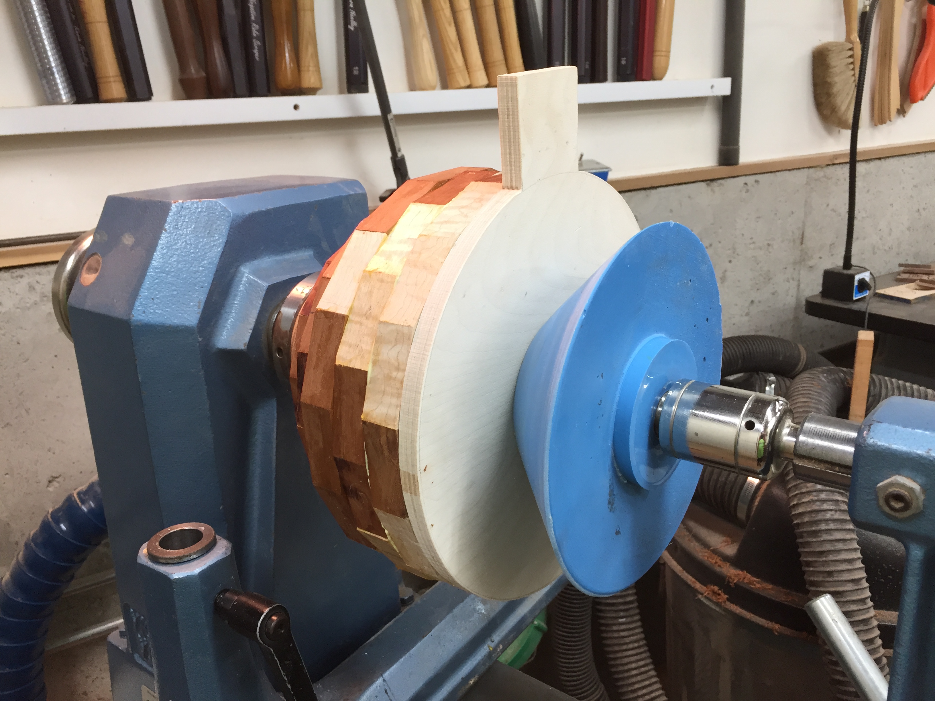
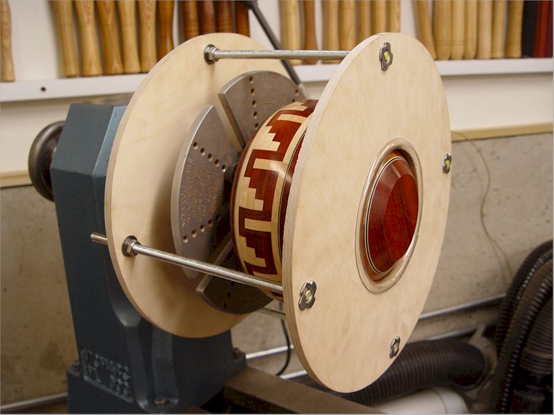
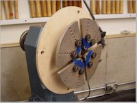
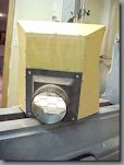
2. This photo is another view of the centering
donut chuck.
|
|
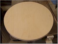
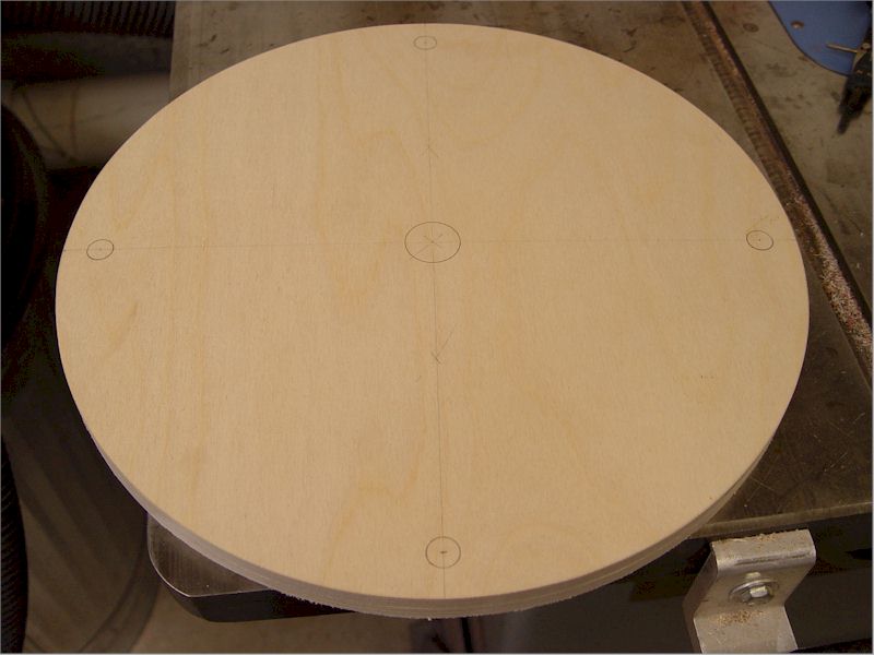
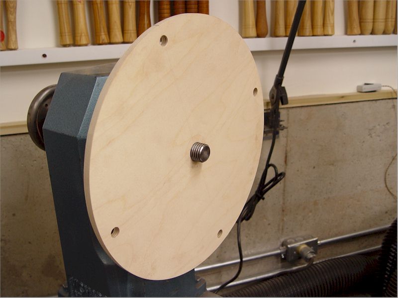
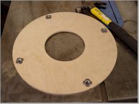
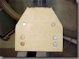
3. This is the rear clamping disk.
The center
hole is my
headstock thread size (1-1/8"). The four all-thread holes are
evenly spaced at 13" centers. Three holes (and threaded rods)
might work equally well.
|
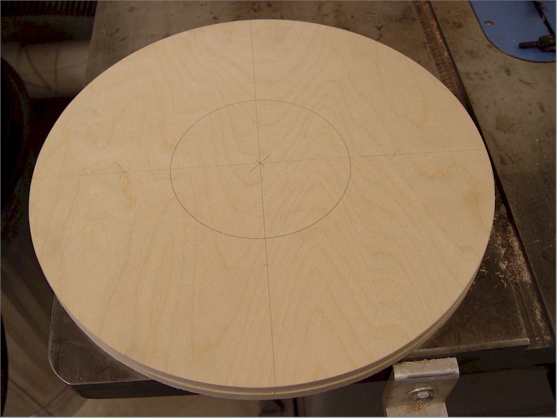
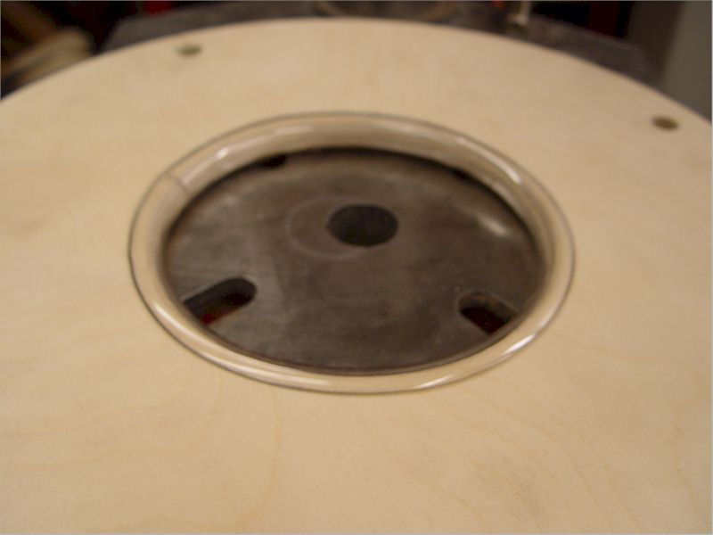
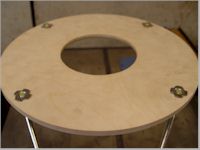
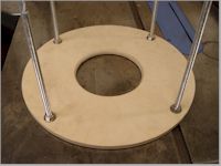
4. This is the front clamping
disk. The
inner hole was
made 5-1/2" diameter (because that's a good size for my
bowls). I
didn't lay out the all-thread holes on this disk because I drill
holes in both disks at the same time using the rear
clamping
disk as the template.
|
|
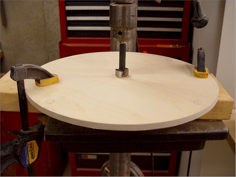
5. A forstner bit was used to drill the
headstock thread
hole in
the rear clamping disk. A board was used to back-up the drill
bit
to prevent tearout.
|
6. The same forstner bit was used to
drill a
starter hole
(in the front clamping disk) for jigsawing the 5-1/2" hole.
|
|
7. The front and rear clamping disks were
clamped together
and
the 29/64" holes for the t-nuts were drilled using a standard drill
bit. Again, a board was used to back-up the drill bit to
prevent
tearout. Note I have made a pencil line on the side of both
disks
to index the holes.
|
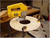
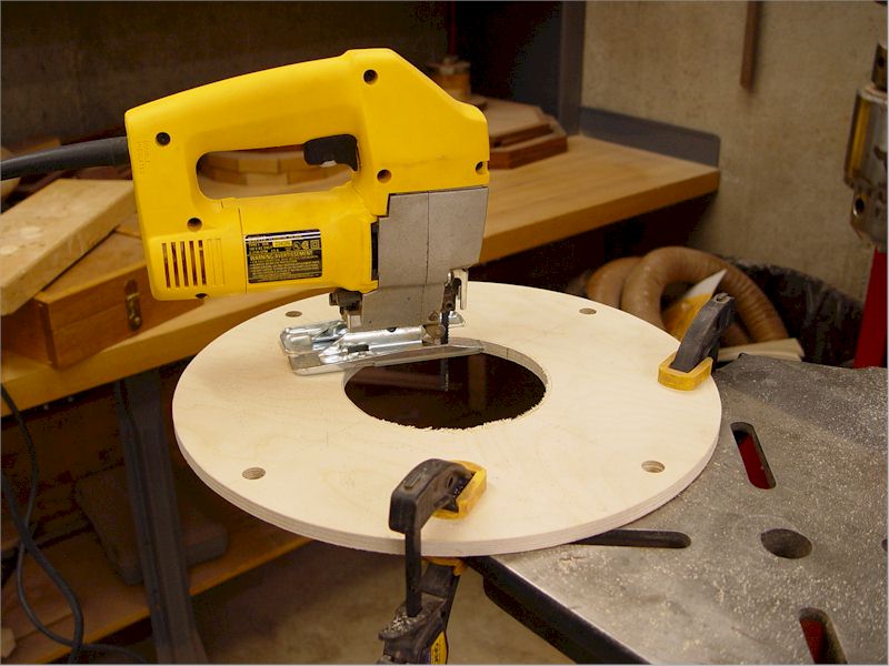
8. A jigsaw was used to remove the 5-1/2"
center hole in
the
front clamping disk.
|
|
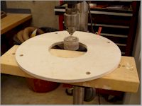
9. A sanding drum on the drill press was used
to round the
center
hole in the front clamping disk.
|
10. The sanding drum was also used to bevel
the inside edge
of the
center opening of the front clamping disk.
The bevel makes it less likely that the plate could
mar the
turning.
|
|

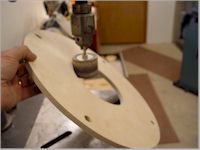
11. A piece of 3/4" clear plastic tubing (from
Ace Hardware)
was
slit and fitted to the center hole of the front clamping
disk.
The hose help protect the turning from the clamping plate
|
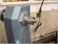
12. A spindle extender might be needed for
extra headstock
clearance and can be purchased from: http://bestwoodtools.com/
|
|
13. Install the rear clamping disk onto the
headstock
threads.
|
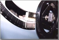
14. Tightly screw the cole jaw chuck onto the
headstock. The
allthread holes in the rear clamping disk do not need to line up with
anything on the cole jaws.
Put masking tape on the cole jaws to protect the bowl
lip. The
rubber buttons are actually One-Way cole jaw buttons, not Nova cole jaw
buttons. I like the One-Way cole jaw buttons a lot
better
than the Nova buttons (they are interchangeable).
|
|
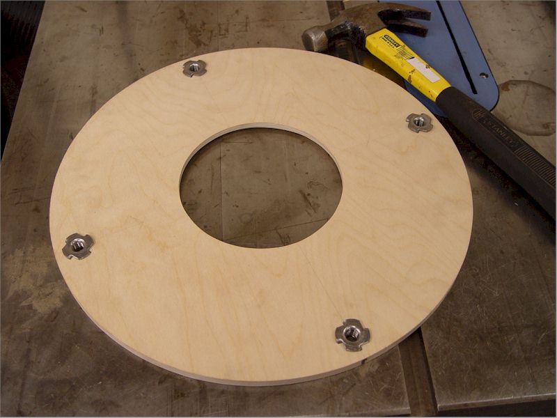
15. With the front clamping disk hole bevel
facing down,
hammer
the 3/8" t-nuts into their holes.
|
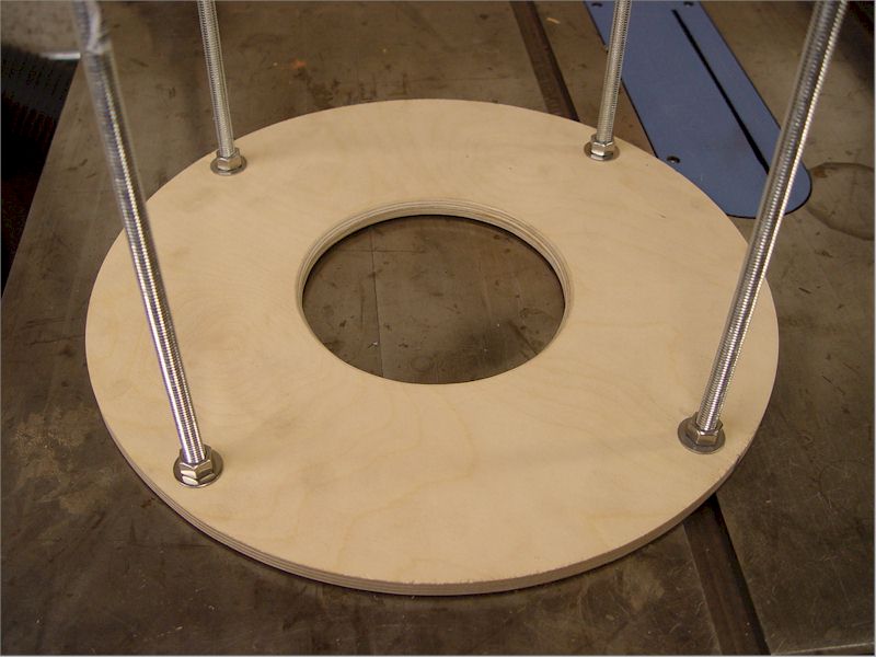
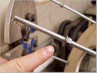
16. Install the threaded rods into
the t-nuts in
front
clamping disk. The ends of the allthread should be
slightly
recessed below the top of the t-nuts.
|
|
17. I used a nut and washer on the backside of
the front
clamping
disk. Tighten the nuts securely.
|
18. Run a nut (with washer) partway onto each
threaded rod.
Hang the front clamping disk loosely on the rear
clamping disk.
Make sure the index parks on the clamping disks are
lined
up.
|
|
19. Note that a nut and washer are run partway
down each
threaded
rod.
|
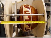
20. Adjust the cole jaws just barely snug on
the bowl lip. I
think
this will center the bowl better than tight jaws.
Engage all the threaded rods and loosely run on the
four
outside (rear disk) nuts.
Start snugging the outside nuts, equalizing the gap
between
the clamping disks.
|
|
21. Don't tighten the inside (rear disk) nuts
until the
outside
nuts are tight and the gap between the clamping disks is equal.
When the disk gaps are equal, tighten the inside nuts by
hand. I don't think you should use a wrench to
tighten the
nuts.
|
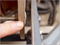
22. The threaded rods shout not hit your
headstock
anywhere.
Give the chuck a manual spin just to make sure.
|
|
23. Set up the tool rest so there is clearance
between the
tool
rest and the t-nuts. Give the chuck a manual spin just to
make
sure.
|
24. Again, make sure there is clearance
between the tool
rest and
t-nuts.
|
|

25. Be aware of the spinning t-nuts at all
times.
They don't
stick out very much, but they will hurt if they hit your
knuckle.
Don't try stopping the chuck from spinning by hand.
|
This square intentionally left blank.
|
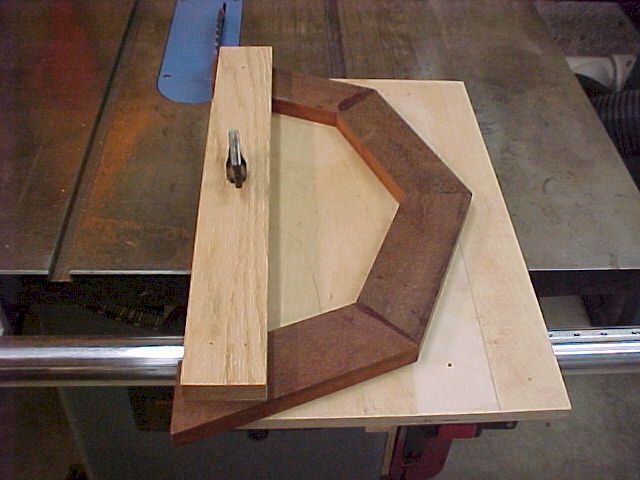
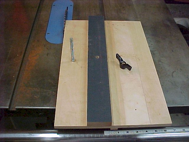
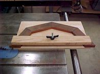
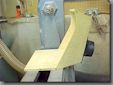
Half-Ring Trim Jig
This table saw jig trims the ends of segmented
half-rings so the half-rings fit together into a perfect
ring.
Alfred Mirman first
mentioned this great idea to me. As you might know from my
website, the way I glue
segmented rings is that I glue segments to make two
half-rings.
Then I sand the ends
of each ring straight and square, using my 12" diameter disk sander, so
the
half-rings fit together perfectly. Most of my segmented rings
have a small enough
diameter so that I can sand the half-ring ends, but some rings have a
greater diameter so
I needed to have another way to true up the ends. The
half-ring
trim jig is the
easiest way to perform this task for rings up to 18"
diameter.
Also, for those
segmented woodturners without a disk sander, this may be a great
alternate method for
making perfect rings.
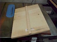
The half-ring trim jig sliding platform is made so
that when
the jig is pushed
past the table saw blade for the first time, the left edge of the
platform is cut to zero
clearance with the blade. After that, anything that overhangs
the
left edge of the
jig will be cut off by the amount of overhang. To use the
jig,
clamp a segmented
half-ring onto the platform, using the holddown, so that the minimum
amount of material
from both ends of the half-ring will be cut off. Cut the
other
half ring the same
way. You might cut one half-ring face up and the other
half-ring
face down just in
case your table saw blade is not perfectly vertical.
Click on
the picture for an
enlarged view.
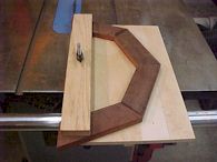
1. A large diameter segmented half-ring has
been clamped
into the
half-ring trim jig. Any half ring material that overhangs the
left side of the jig will be cut off.
|
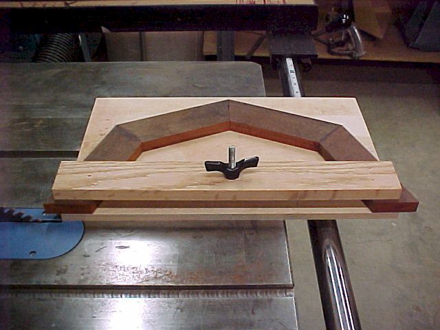
2. Another view of the half-ring trim jig.
|
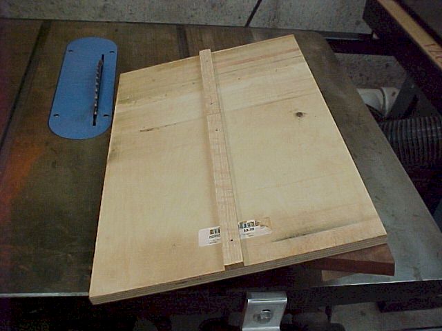
3. The underside of the half-ring trim jig,
showing the
runner. The runner must allow free movement in the miter slot
but
not have a sloppy fit.
|

4. I have glued sandpaper to the underside of
the jig
holddown so
the segmented ring won't slip while cutting.
|
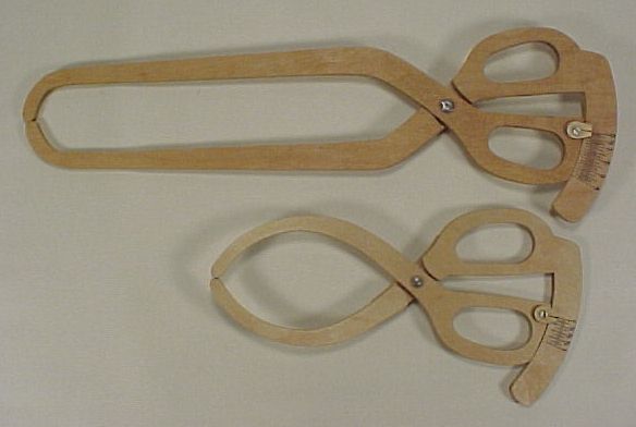
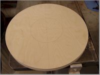
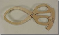
Bowl Wall Thickness Caliper
I have made a number of special-use wall thickness calipers. Some are
for deep or unusual-shaped bowls. I originally tried to buy thickness
calipers but none of them were exactly what I wanted. Either the
calipers in the catalogs weren't shaped right, didn't have a
measurement scale, or maybe couldn't be used one-handed.
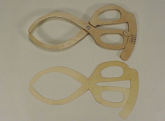
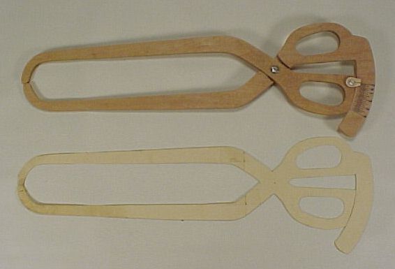
These calipers are made from 1/4" baltic birch
plywood. I used
an old pair of
tin snips for my handle design shape. The caliper jaw shapes came from
my imagination and
from the calipers intended use. The scale doesn't need to be too big
for general bowl
thickness use. The scale reads 1" to 0" by 1/16ths of an inch.
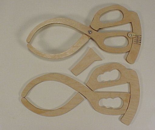
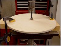
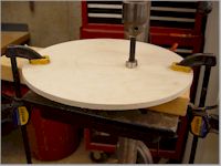
Each caliper starts out as an outline drawn on
construction
paper. Next I trace
the five caliper component sections onto the plywood and cut it out
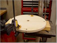
using my bandsaw. Then
I rough-drill the handle holes using forstner bits. Next I glue the
3-piece scale section
together and install a pivot screw. I sand the parts smooth with a
sanding drum chucked
into my drill press. The scale pointer, made from a handy wood scrap is
then installed
with a small screw so scale zero can be adjusted if necessary. I
calibrate my caliper
scale by closing the caliper jaws on known thicknesses, then marking
the caliper scale.
Caliper calibration needs to be done this way because, since the
distance from the
caliper's pivot screw to jaws is usually larger than the distance from
the caliper's pivot
screw to scale, the 0" to 1" mark width of the caliper's scale will
usually be less
than 1 inch. I calibrate my calipers using the jaws of a dial
caliper, but it could
also be done by careful use of a ruler.
Click on any photo to enlarge it.
|
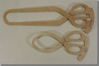
The long caliper was made for a deep
jar, like
#454 on my Lidded Jars webpage. The shorter caliper was made for short
bowls, like #622 on my bowls webpage.
|
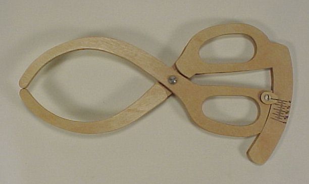
The small caliper.
|
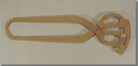
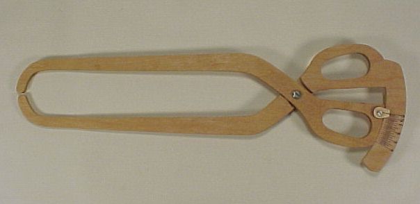
The long caliper.
|
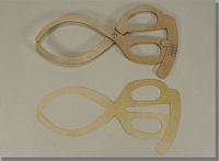
The construction paper outline of the small caliper.
|
The construction paper outline of the long caliper.
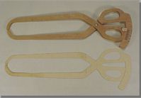
|
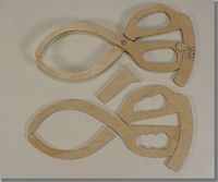
This photo shows the rough sawn 5-piece small caliper
sections.
|
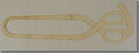
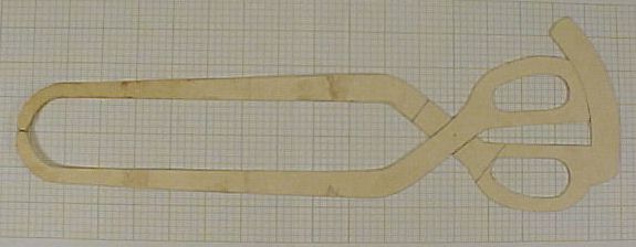
I photographed the long caliper construction paper
outline
against 1" x 1" graph paper.
|
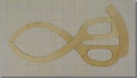
I photographed the small caliper construction paper
outline
against 1" x 1" graph paper.
|
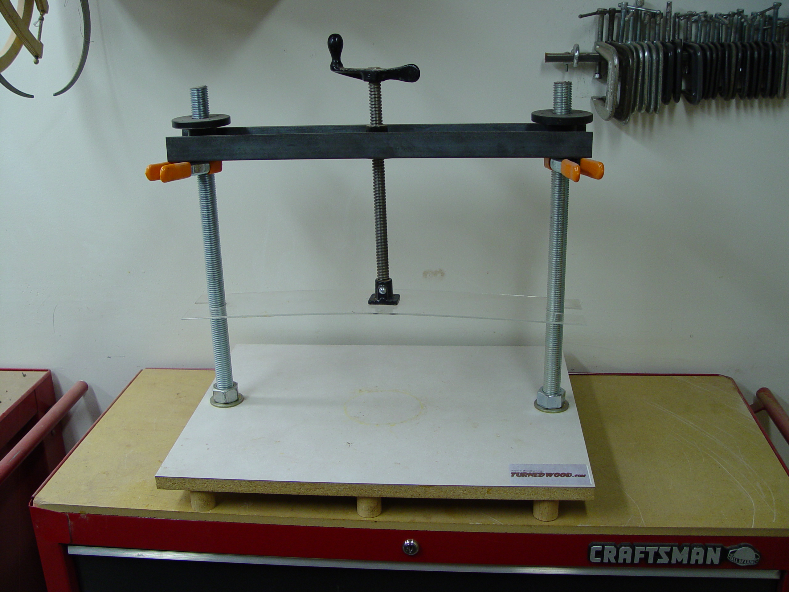
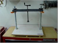
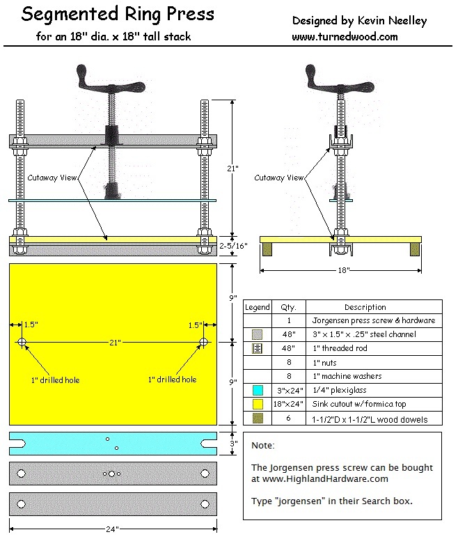
Segment Ring Press
This ring press works
great and it doesn't involve any welding. You can buy the
metal
cut to
length at a "metal-by-the-foot" outlet. I would like to thank
Jeff Crews for the
idea of using an anti-twist plate to reduce the screw's twisting action
on the glue-up and also locating a good source press screws.
These are pretty standard presses and are made
primarily from 3"
steel channel and 1" threaded rod (3/4" threaded rod works well,
too). I have seen these ring presses made entirely from wood
and,
if made strong enough, should work fine.
Ring Press Photos updated 8/25/12 - Click on the
photo for an
enlarged view:
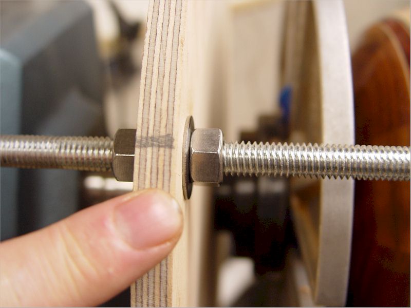
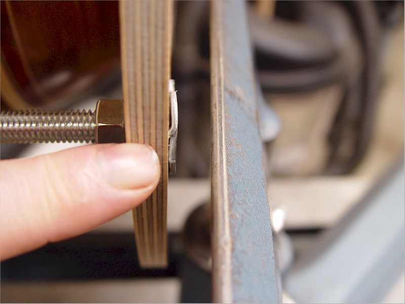
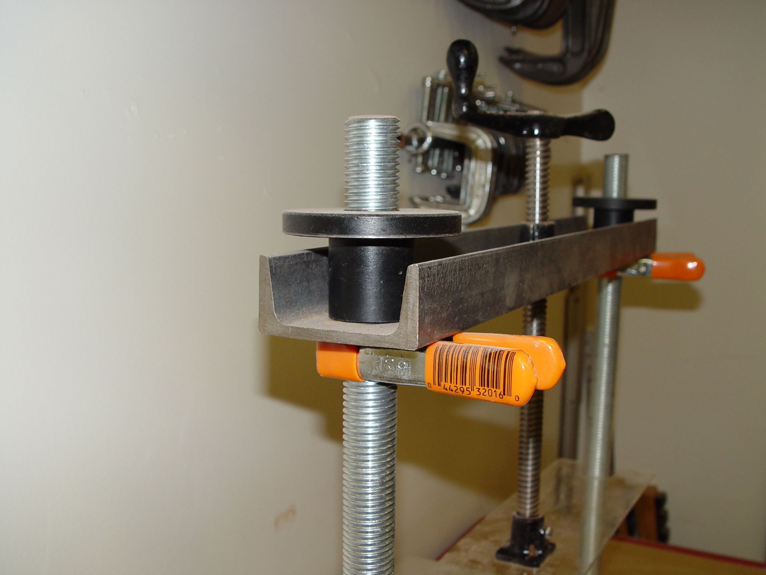
The updated Ring Press uses small spring clamps instead of the lower
nuts. The other change is using cheap lathe faceplates instead of the
upper nuts. These upxdates speed up clamp height changes. |
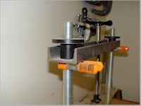
A closer view of the spring clamp and faceplate.
|
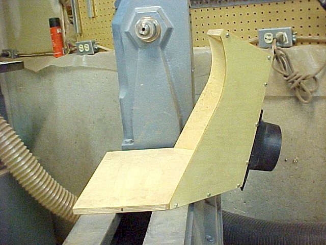
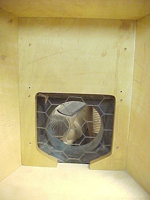
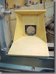
Lathe Sanding Hood
I made this lathe
sanding hood to fit my 24"
Vicmarc lathe. I
think it will work on a bowl up to 23" diameter but I haven't tried it
on
that size yet. If you make one of these, the side panels can
be
straight
instead of having a curved cutout.
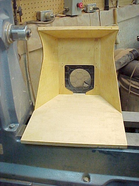
The plastic part where the
dust collector hose
attaches is
called a "universal dust hood". Here is a link to this part
at Highland Hardware: click
here. A piece of chicken
wire was sandwiched into
the duct
opening to screen out dropped sandpaper.
The angle of the back is 15 degrees, which is
optional.
The angle
of the sides are 30 degrees, which I think is necessary to properly
funnel the
dust into the collector. The angle of the top is 15 degrees,
which is
probably optional. The top, back and base are made from 1/2"
baltic
birch plywood. The sides are made from 1/8" baltic birch
plywood.
Feel free to make material substitutions. When I constructed
the
hood, I
assembled the top, back, and bottom (screwed together, not glued)
then used these pieces to make an outline for the sides.
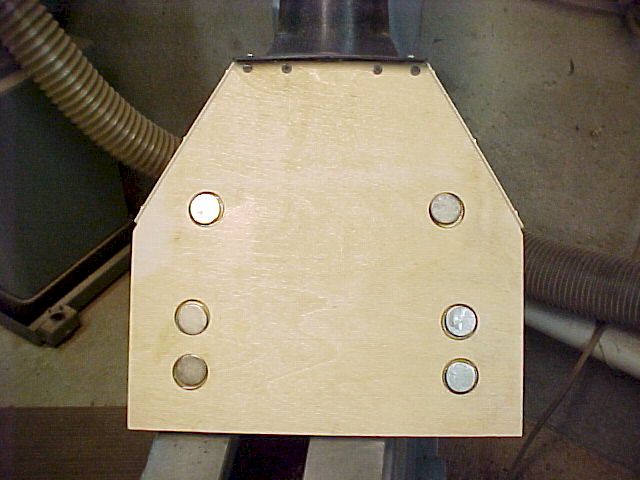
To attach the lathe dust hood to the lathe bed I
used six
1" diameter magnets (the pack contained six). Here is a
link to this part at Highland Hardware: click
here.
Click on any photo to enlarge it.
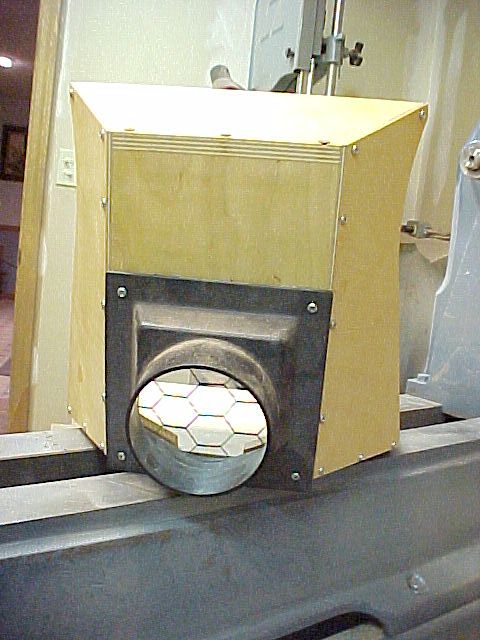
The sanding hood attaches to the
lathe bed using
magnets so it can be moved around and removed quite easily.
|
The front of the sanding hood top
should be moved
very close to the turning while sanding. This traps the most
dust.
|
A chicken wire screen prevents
sandpaper and
other bad things from being pulled into the dust collector.
|
The sanding hood has a factory-made
dust port. My
4" dust hose uses a quick connector I bought at Woodcraft Supply.
|
I used six rare earth magnets in
this pattern.
|
This
cell was
intentionally left blank
|
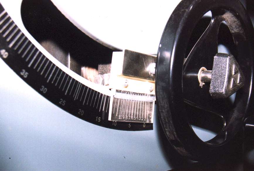
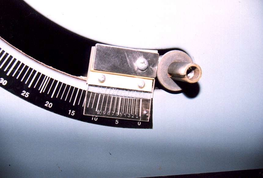
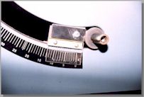
Table Saw Blade Angle Vernier Pointer
This is a photo
of a blade
tilt angle pointer I made for my Delta table saw. I replaced the
original cheap tin blade angle pointer with this vernier scale pointer.
I used the
original blade tilt angle scale, which is graduated in degrees. The
vernier pointer
divides each degree into tenths of a degree, so the vernier pointer
makes it possible to
accurately move the blade tilt by tenths of a degree so table saw blade
tilt angle can be
set to within 1/10th degree accuracy. After the table saw blade has
been adjusted exactly
square, the vernier pointer is adjusted to zero on the table saw's
blade tilt angle scale.
That's all the calibration necessary.
Click on any photo to enlarge it.
The vernier scale pointer exactly replaces the original
cheap
tin pointer.
|
I have removed the blade elevation handwheel to show
more
detail on the vernier pointer.
|
The scale
is scribed into the back
side of 1/8"
plexiglass using a compass foot needle. I used the back side of the
plexiglass because it
was very close to the front side of the saw's angle scale and this
would reduce parallax
angle errors.
I got the idea for making this vernier pointer from
my friend George
"Sonnie" Sharrar, who made a table saw compound and frame miter-cutting
sled
that featured a
vernier angle scale. His sled was very well-designed and I was
impressed with his vernier
scale accuracy, so I borrowed his idea.
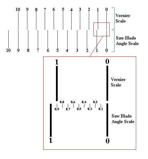
The lines on the vernier scale
are not every
1/10th degree, they are
every 9/10th degree. I scribed the zero-to-ten degree segment of the
blade angle scale
from my table saw onto the piece of plastic, a tick mark for zero and a
tick mark for ten
degrees. Then, a friend of mine used a CAD program to print radius
lines on a piece of
paper, like spokes on a wheel, every degree for 360 degrees. I matched
up the plastic
9
degree arc with 10 of the paper radius lines so that the 9 degree saw
scale arc was
divided into 10 sections. I then scribed the 10 marks into the plastic.
Now, every
division on the plastic would be 9/10th degree.
I mounted the plastic vernier scale over the table saw scale, replacing
the old tin angle
pointer, so that the 9-degree saw scale could be seen through the
10-section plastic
vernier scale, and the vernier scale move with the blade tilt
mechanism. I adjusted the
vernier scale by lining up the zero tick marks of both saw and vernier
scales exactly. So,
the first tick mark on the table saw scale is 1 degree, and the first
tick mark on the
vernier scale is 9/10th degree.
The way the vernier works is,
when the saw blade
is tilted so the
first saw scale tick mark and the first vernier scale tick mark line
up, the blade has
been tilted 1/10th degree. So, when the saw blade is tilted so the
second two pointers
line up, the blade has been tilted 2/10th degree, etc.
Of course, the scribe marks need to be layed out fairly exactly or the
new vernier scale
won't be very accurate. You should be able to visually judge if the
vernier scale is
accurate when it's installed for the first time.
This page and
its source code is
Copyright 2026 by Kevin's Woodturnings
All rights reserved. World rights reserved.